
ECG Analog Front End Design
Resources:
Analog Front End Design
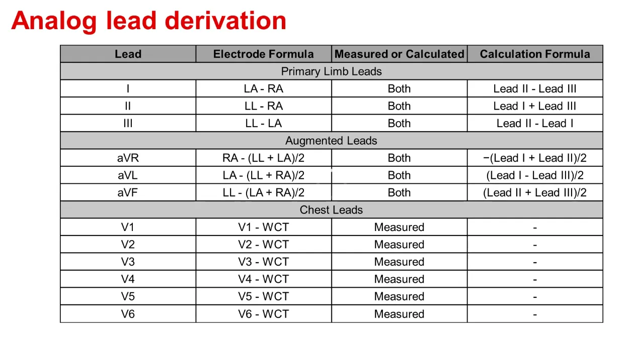
Analog Front End Circuits
- https://www.eevblog.com/forum/projects/ecg-front-end-design/
- http://engineerslabs.com/2012/01/ecg-circuit-analysis-and-design-simulation-by-multisim/
- https://medcraveonline.com/IJBSBE/IJBSBE-02-00032
Instrumentation Amplifiers
- http://www.ti.com/lit/an/slyt226/slyt226.pdf
- Bonus Read : https://www.edn.com/electronics-blogs/bakers-best/4312741/Understanding-CMR-and-instrumentation-amplifiers
- Bonus Read: https://www.edn.com/design/analog/4322833/The-right-way-to-use-instrumentation-amplifiers
ECG Filters
Also check out my other post on filter design resources.
ECG Analog Front End design :
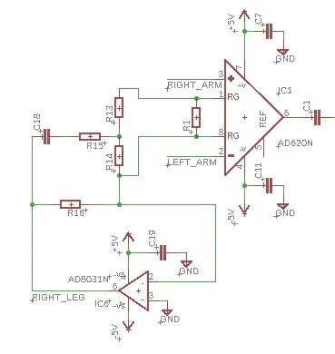
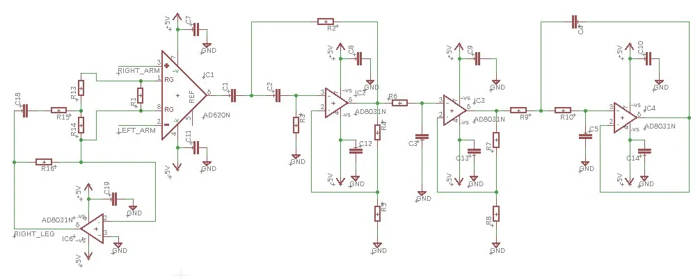
After reading quite a lot about instrumentation amplifiers and checking out many datasheets, I went for the popular AD620 instrumentation amplifier for this design.
I used the following filter design wizard from AD. Though I’d tried TI’s WEBENCH I found the interface too clunky and complicated (Update : 10/2/2019 : Heard they’re taking down WEBENCH and coming up with a modern tool).
https://www.analog.com/designtools/en/filterwizard/
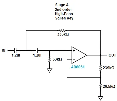
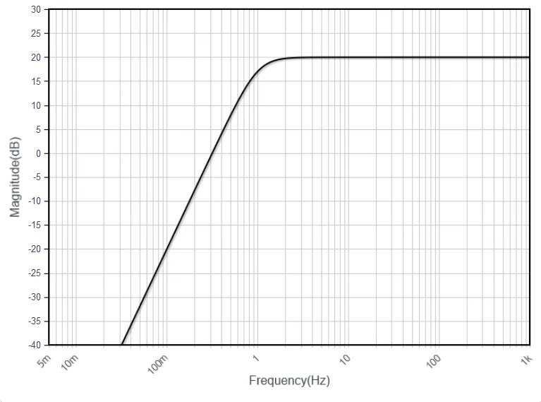
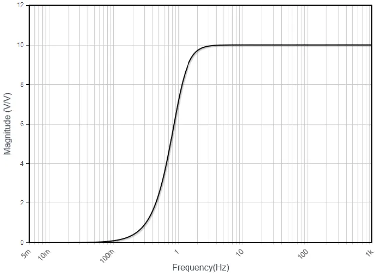
High Pass Filter
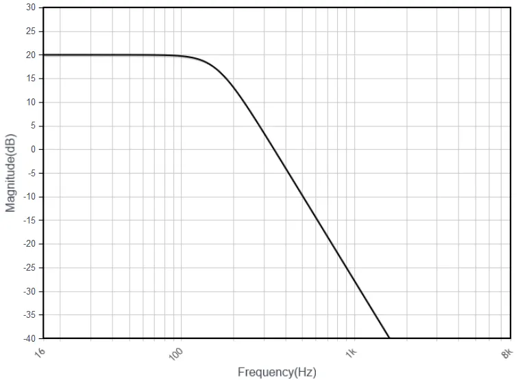
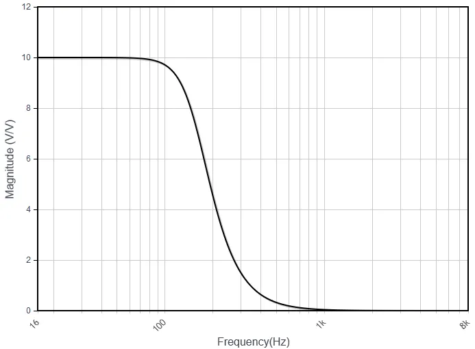
Low Pass Filter
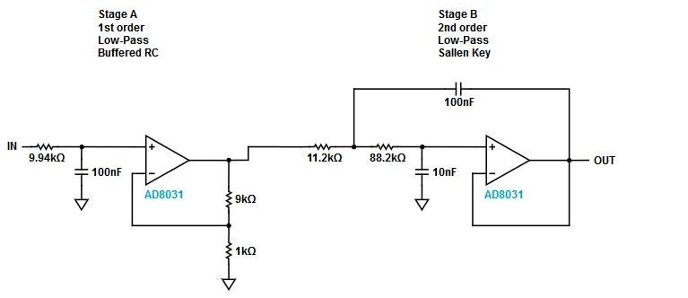
Here are the .json files of the filter design on Analog Devices. To make use of the design, please extract the contents of the archive and use the load functionality of the Analog Filter Wizard application.
https://drive.google.com/open?id=1Y4Tmg_Hab5k2O6HNuWMNP2K-eRkw4oZO
https://drive.google.com/open?id=1Jzop1DJHNJYrhrkWfAgfsLzyc-h-l0OZ
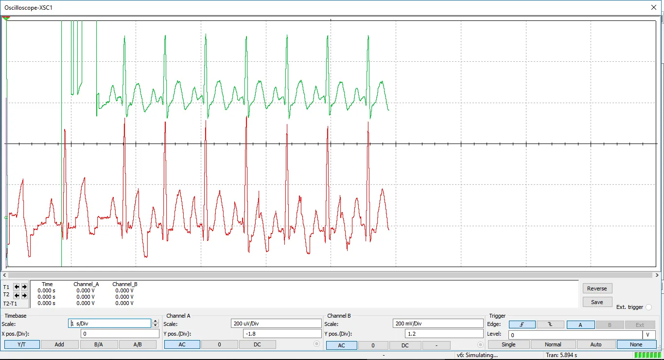
The circuit was simulated on Multisim as it had an ECG source Virtual Instrument (VI) which made adding inputs and testing very easy. Also check out one of my earlier posts on ECG sources for PSPICE, TINA, Multisim
To request a free student license of Multisim: https://forums.ni.com/t5/Projects-Products/Free-6-Month-Evaluation-of-LabVIEW-Student-Edition-for-at-home/ta-p/3497362
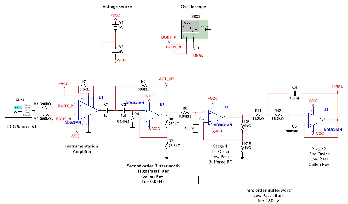
The simulation is pretty slow and takes about 5-10 mins for just few seconds of output waveform.
To complete the design a right leg driver is also required. I found a sample design in the AD620 datasheet. Refer the datasheet for component values.
Find the Eagle schematic files below. I haven’t added any component values so feel free to modify the design. I’ve also included the designed PCB board file which can be used to print PCBs of the design. When viewing the board file it’ll be obvious that I left from space in the design. This space can be used to fit your ADC or microcontroller as required.
Schematic: https://drive.google.com/open?id=1SmVk-UKjU5Txz7n4XtXaLR8sn5X_m8Hd
Board file: https://drive.google.com/open?id=1H9TMdvzQbodYp-KvaYcD_jdl-GM3h0sv
Bonus read:
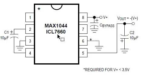
Making the Dual voltage supply rail (the above EAGLE files include this)
EESE to the rescue : https://electronics.stackexchange.com/questions/79307/what-are-the-ways-to-make-a-dual-power-supply-from-a-single-voltage-source
Decided to go forward with the MAX1044 IC because of it’s simple voltage conversion:
ADC
- ADC interfacing : http://www.ti.com/lit/an/slyt173/slyt173.pdf
- Choosing the right ADC : https://www.ti.com/europe/downloads/Choose%20the%20right%20data%20converter%20for%20your%20application.pdf
Comments