Variable frequency PWM generator
I scavenged this cooling fan from a laptop.
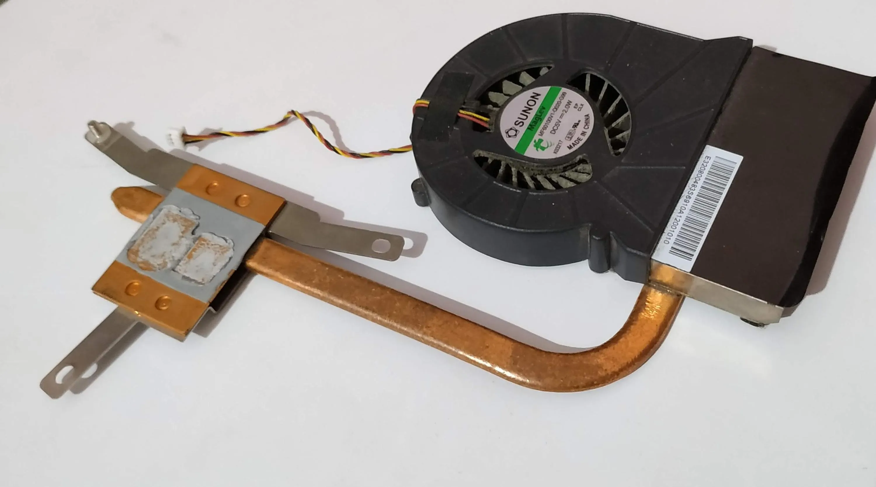
So this runs on a PWM signal and since it needs 2W I can’t run it off a microncontroller pin without frying it. So I decide to make an external PWM circuit.
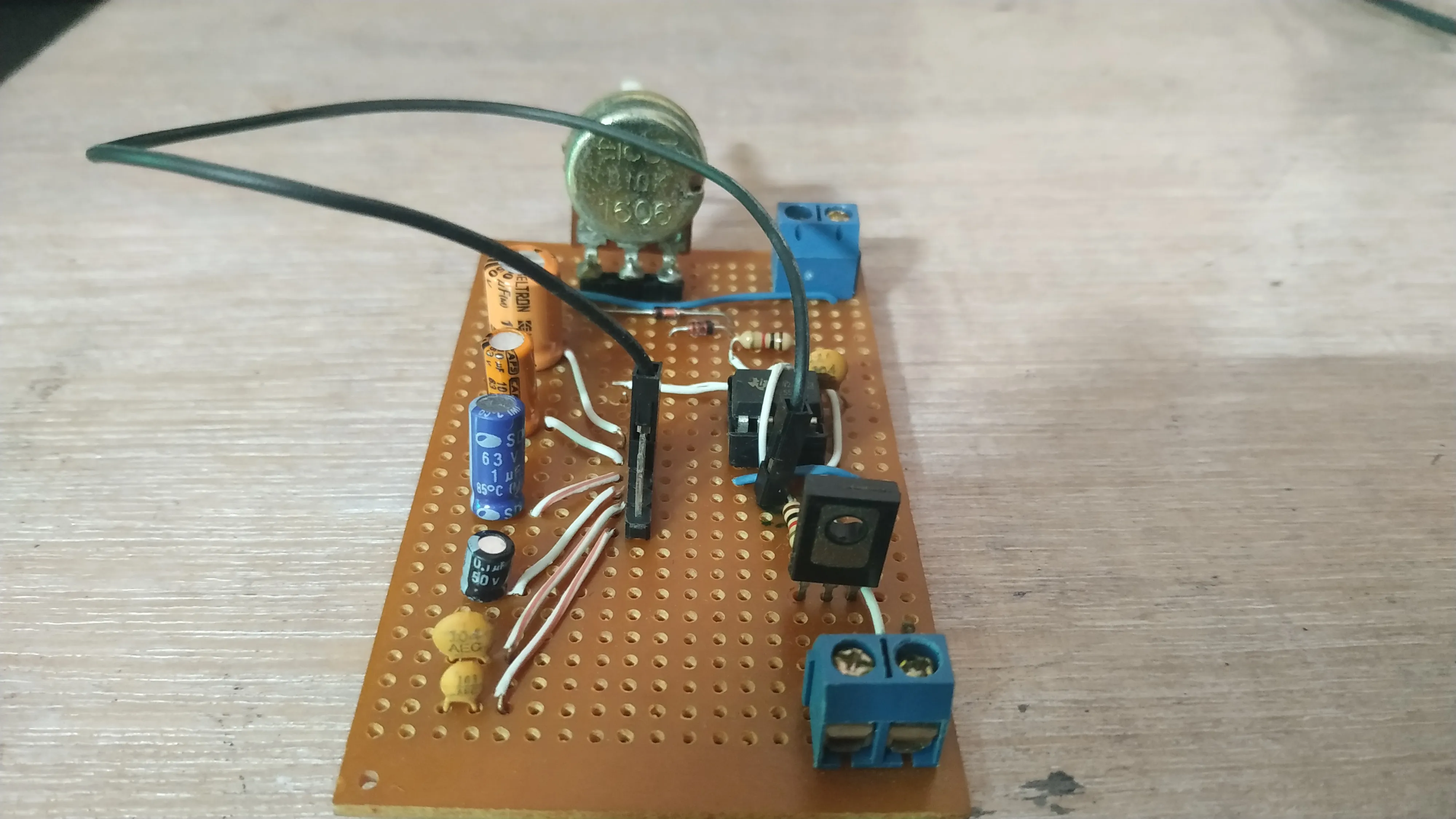
Initially, I thought about making a PWM circuit for just this specific function using a simple timer circuit. Then I thought, why not add in a few more caps and make it work at multiple frequencies. The possible applications include - testing servos or control valves, running motors like this and testing everything else that uses PWM.
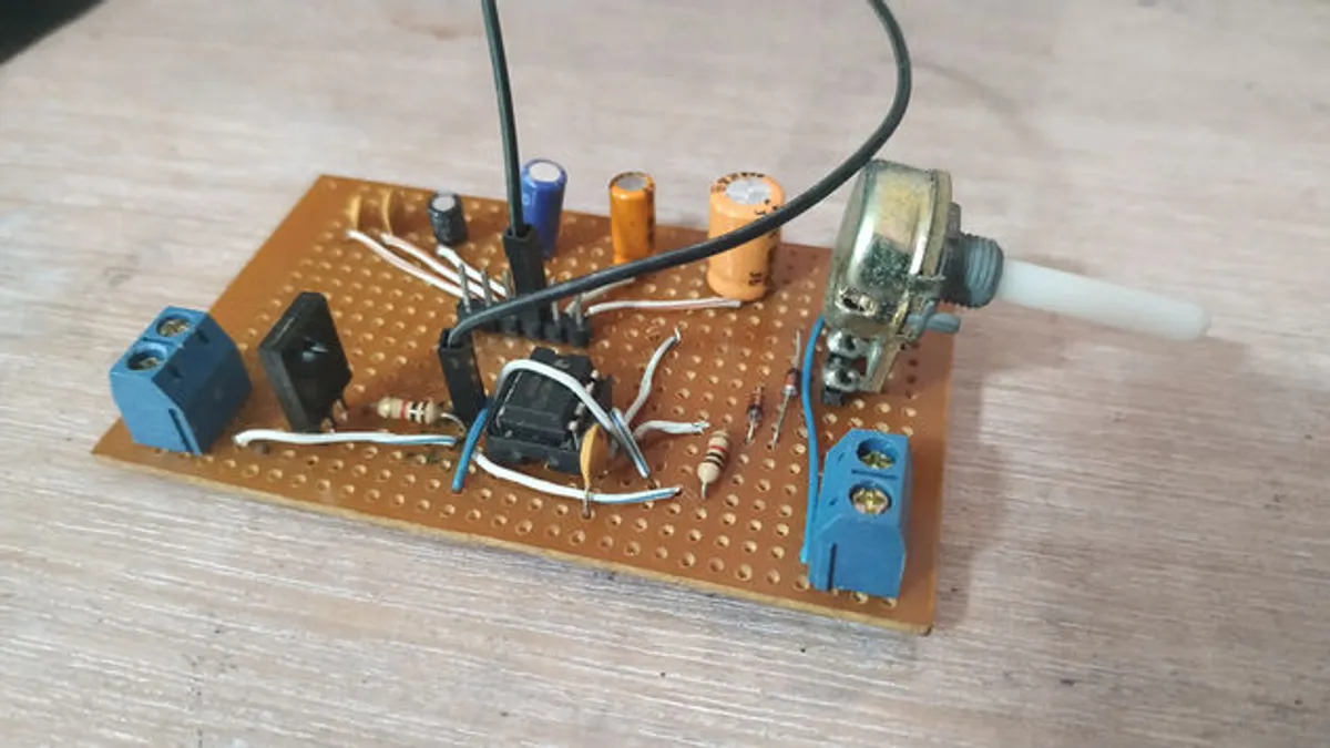
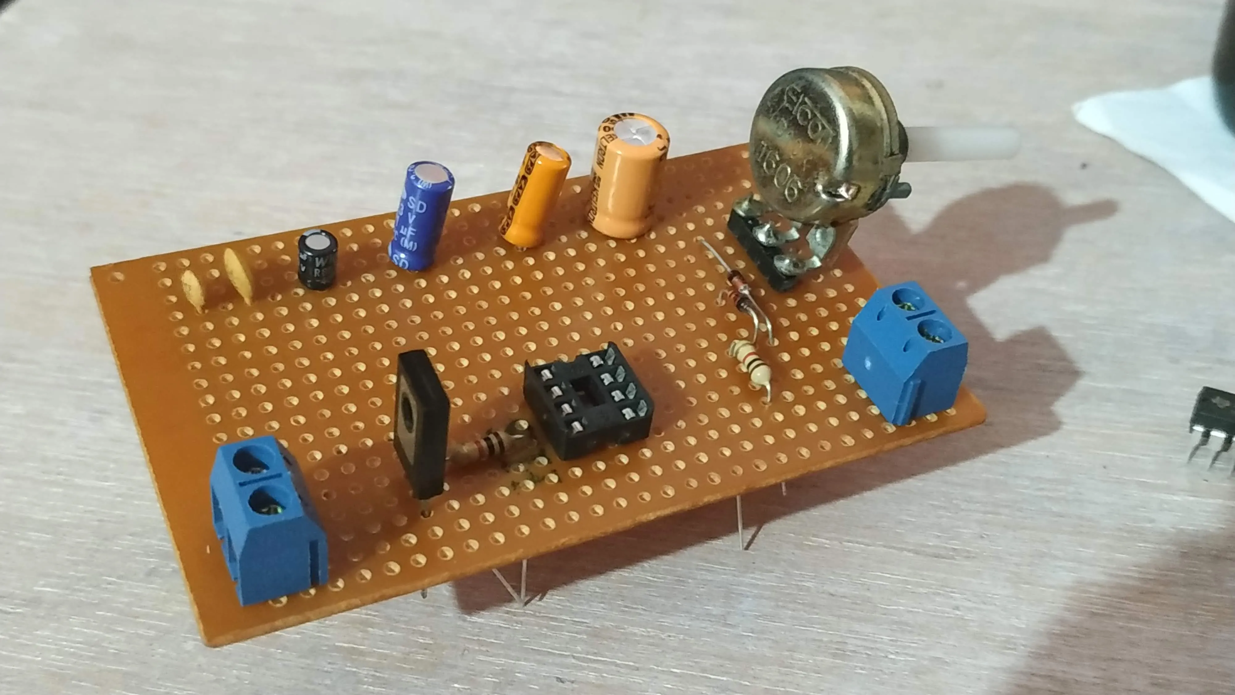
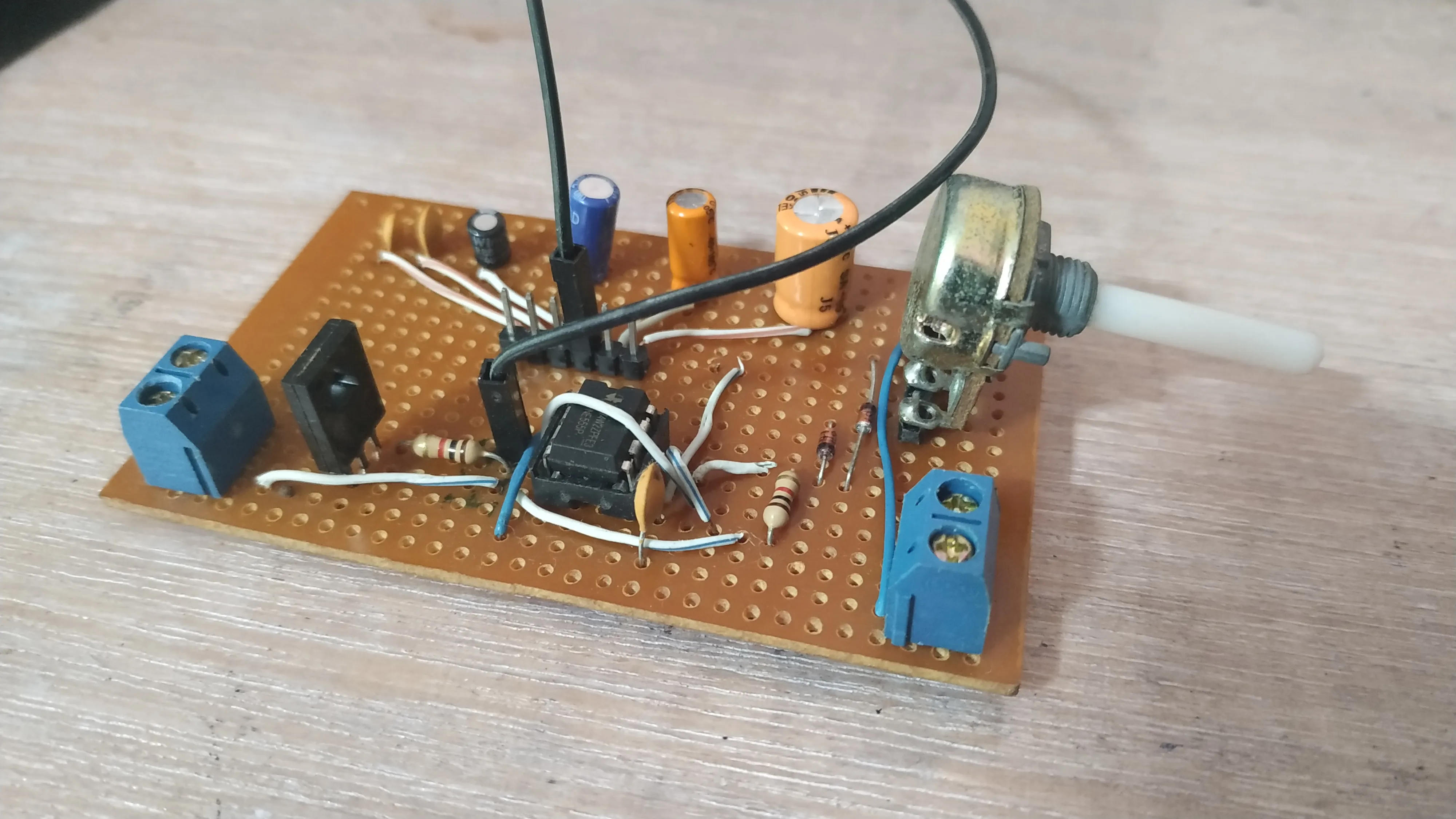
When I was checking the NE555 datasheet I found that the max. current rating of the timer IC was 200mA and that was below our requirement. Hence a transistor was necessary to drive the required amount of current. My search led me to this circuit on instructables. So this guy had already made a high frequency PWM. I also had a BD139 transistor around. I followed the schematic and added extra caps and terminal blocks.
Note: The instructable suggests that any general purpose diode can be used. The author used a 1N4148 diode. But I’d like to clarify that only signal diodes like the 1N4148 can handle high frequencies. If you go with the most common general purpose diode the 1N4007 I don’t think it can handle large frequencies due to their large reverse recovery times.
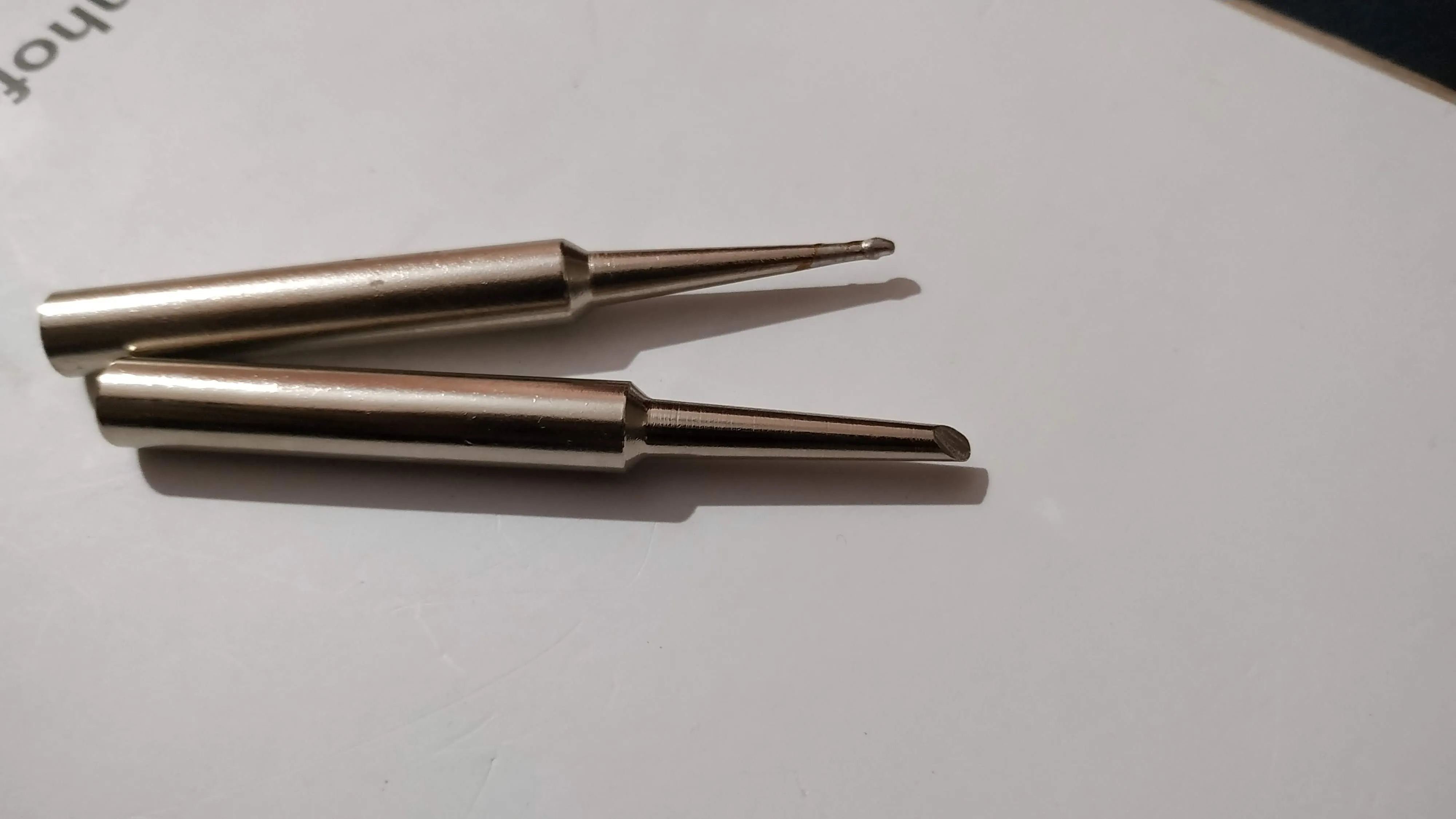
Just going to try soldering the circuit with my new soldering tips.
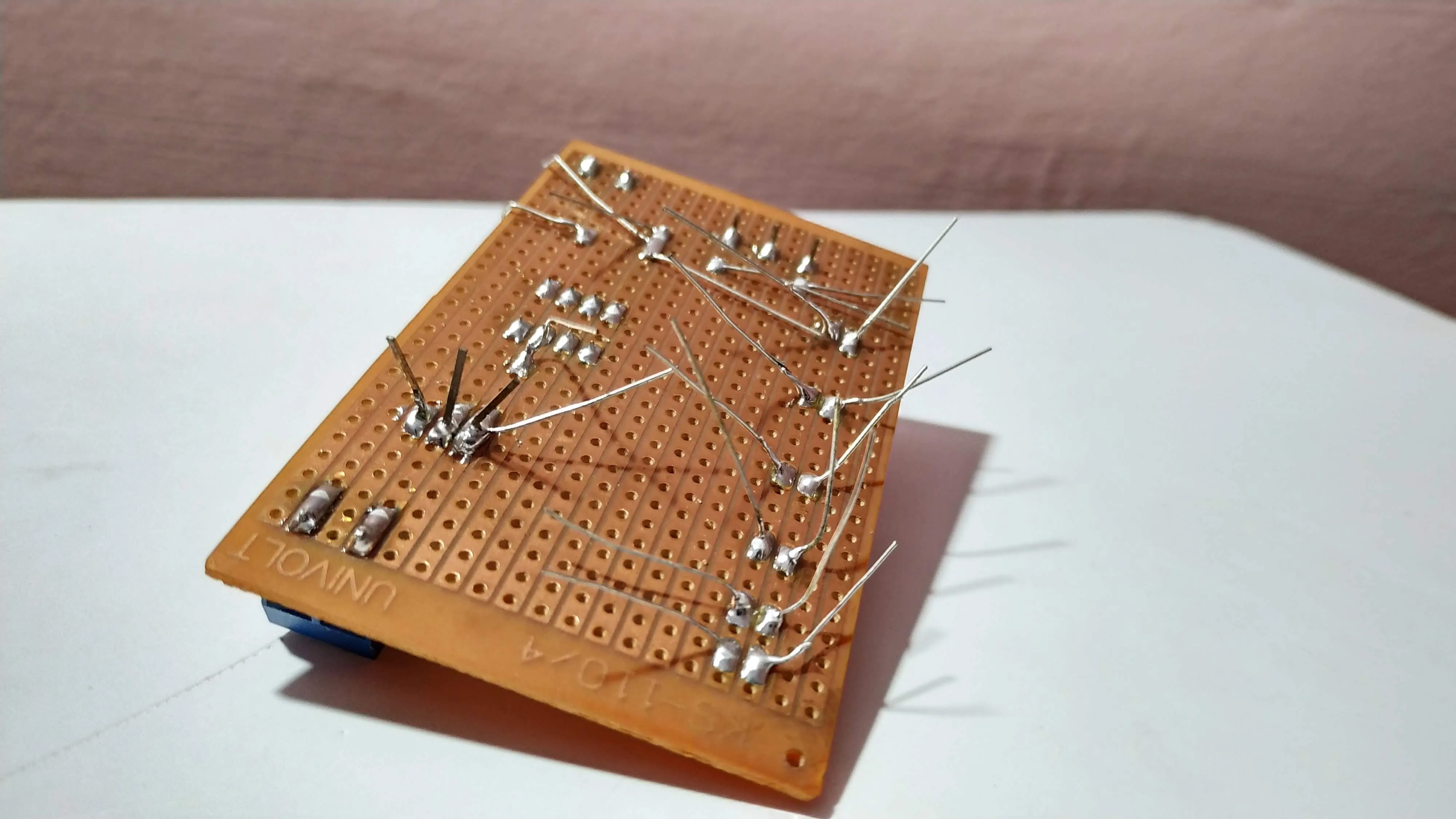
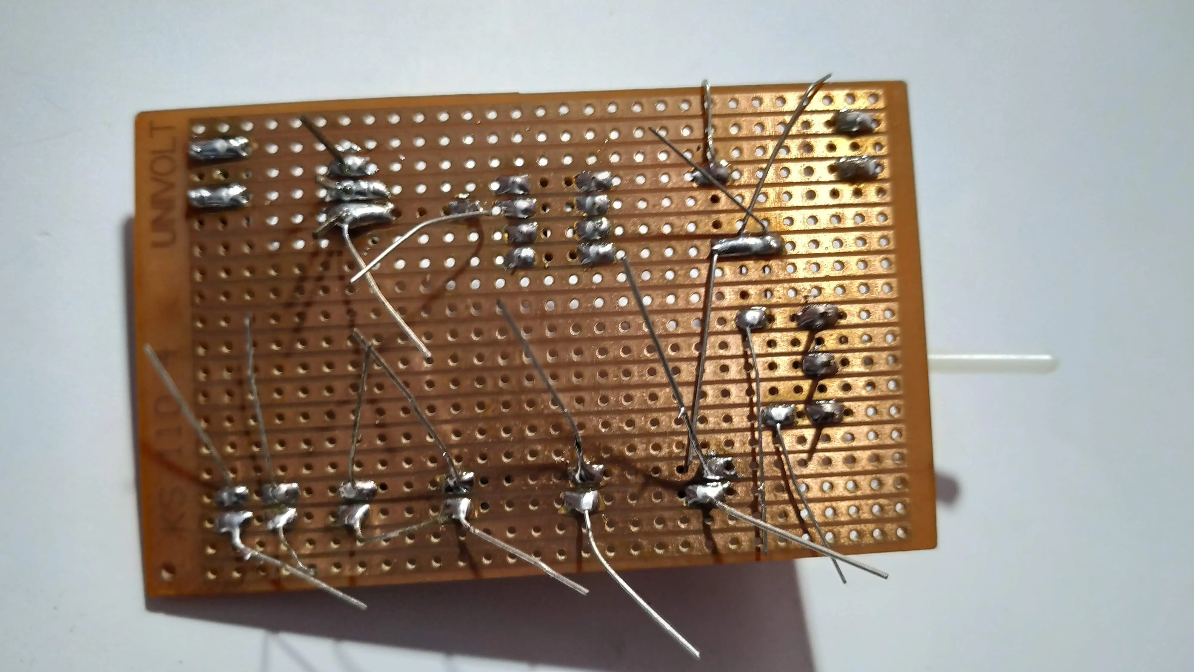
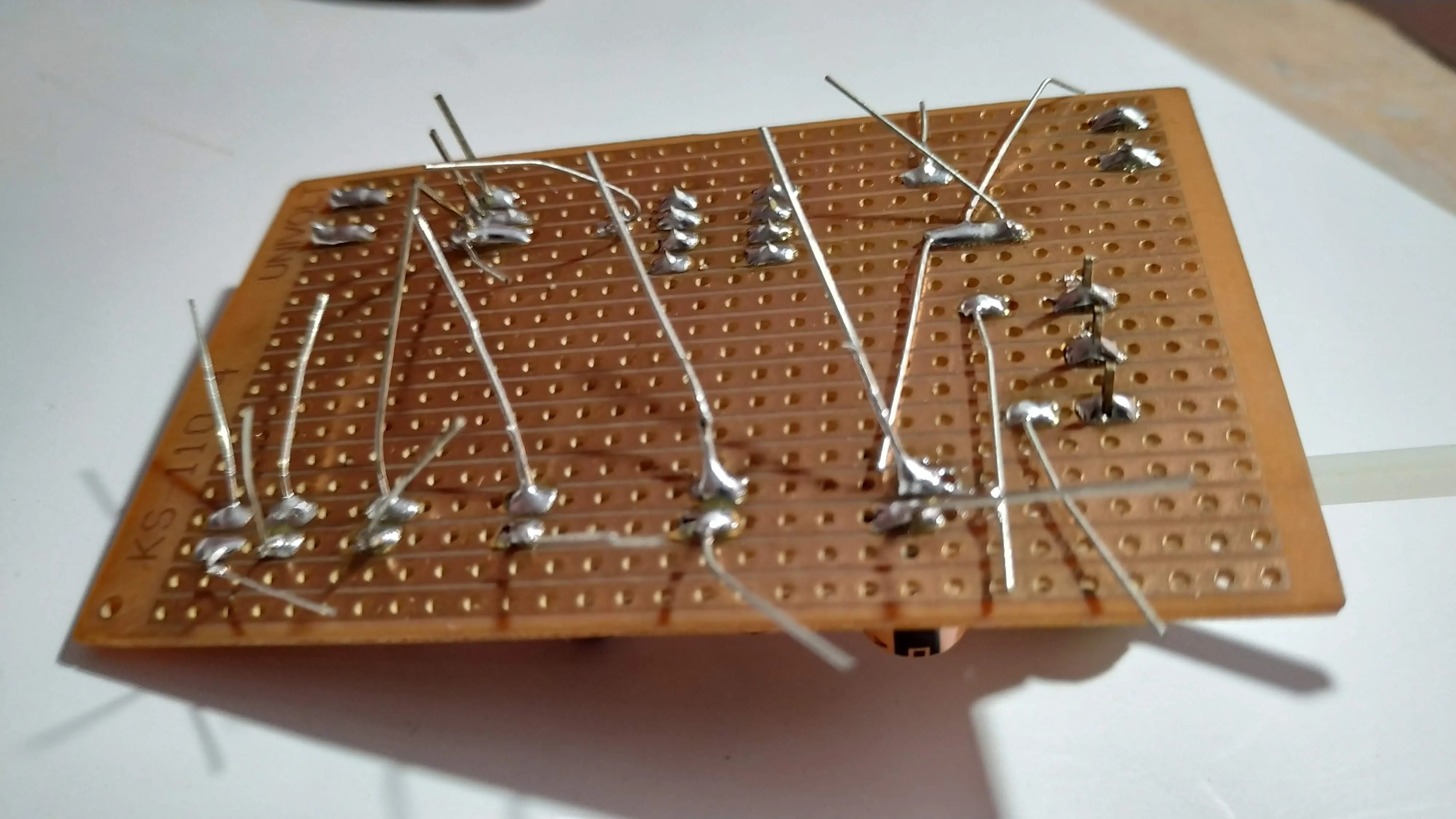
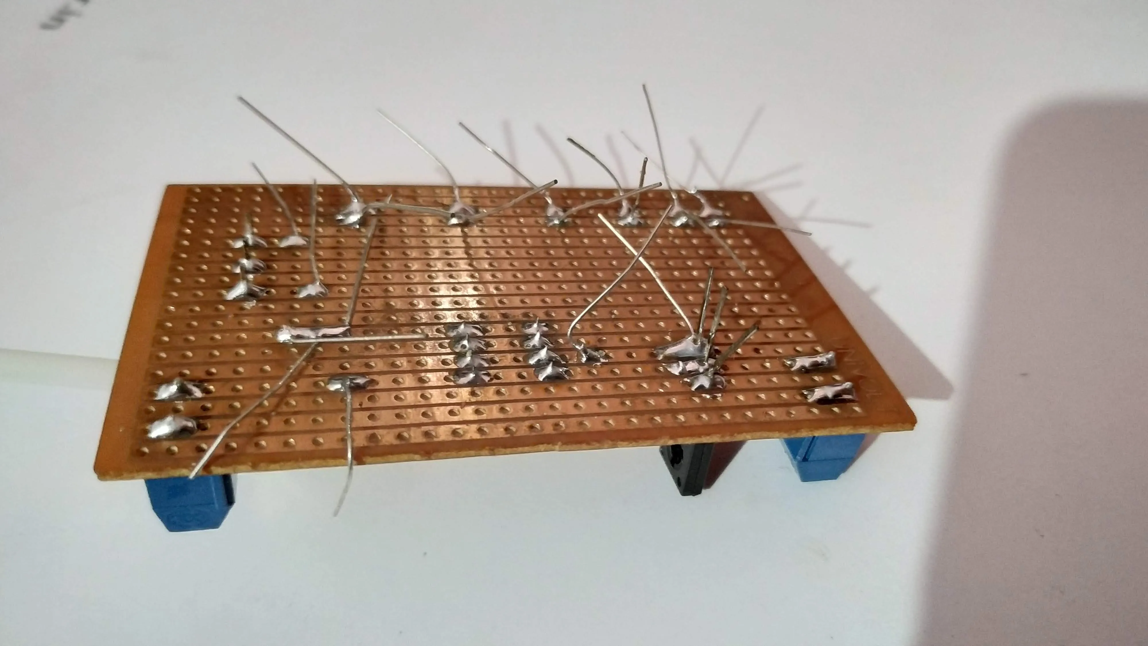
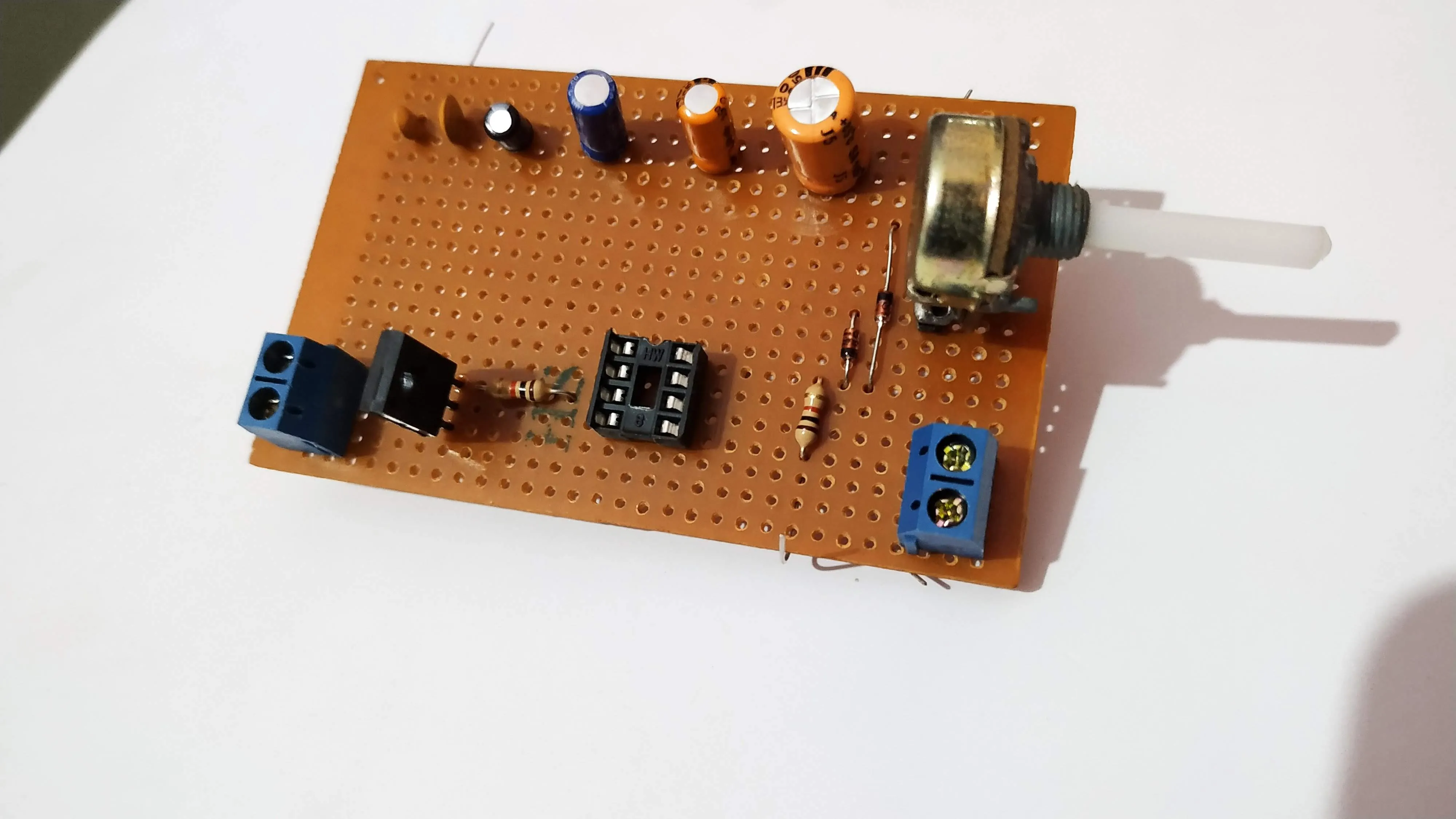
Phew this is the last time I’m going to buy perforated boards with straight lines of copper running along the length of the board. It’s such a hassle to scrape off copper to break unnecessary connections. It’s always better and easier to create solder bridges. 😌
Comments