A DVD player at stake!
It was time to bid goodbye to an old Phillips DVD player.
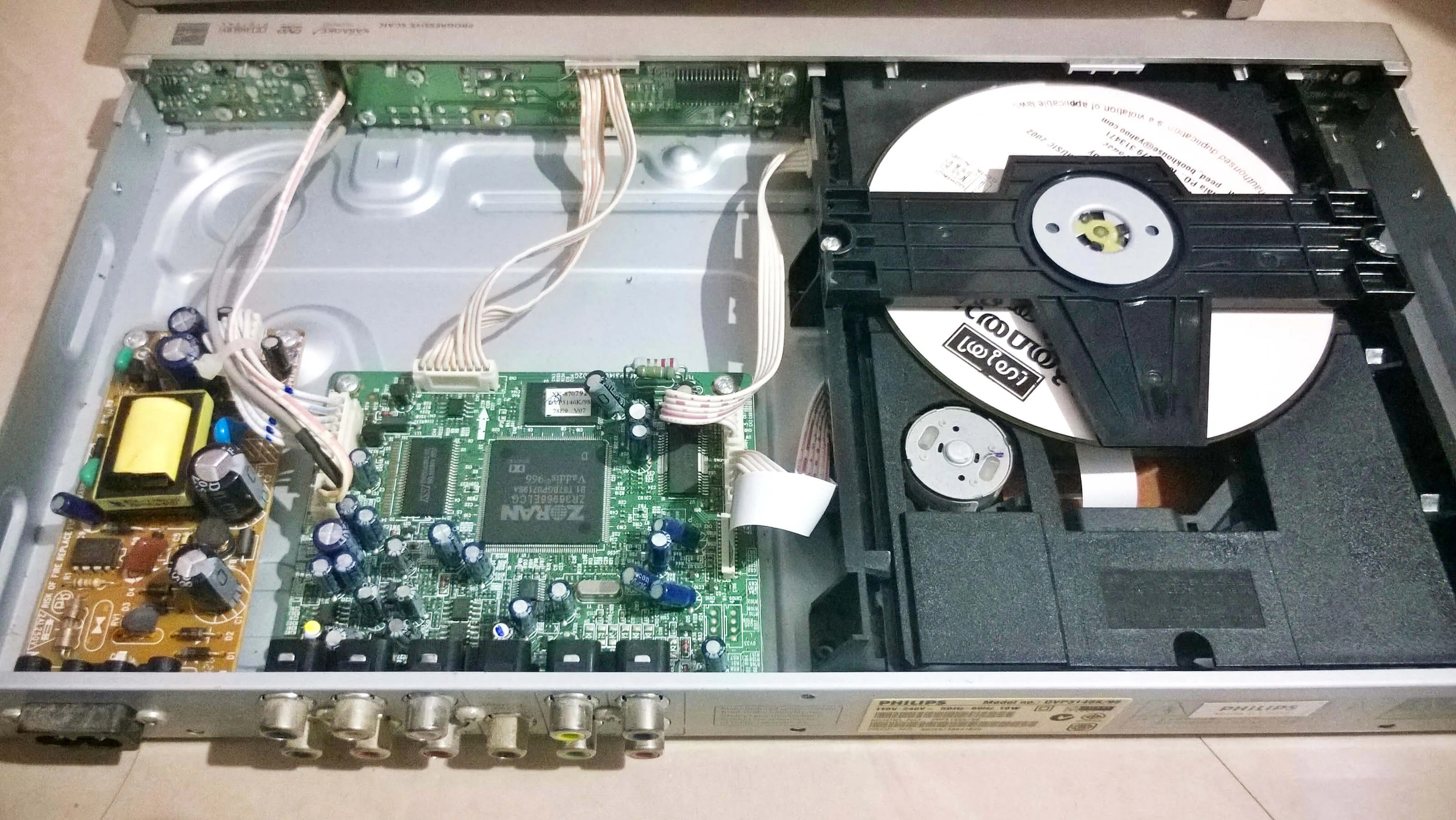
Removed the AC main cable and unscrewed the enclosure.
⚠️ Ensured that all the capacitors are safely discharged by touching them with a metal part. ⚠️
Then I looked for its service manual (thankfully I found it here) and followed the part removal procedure.
Took things apart one be one.
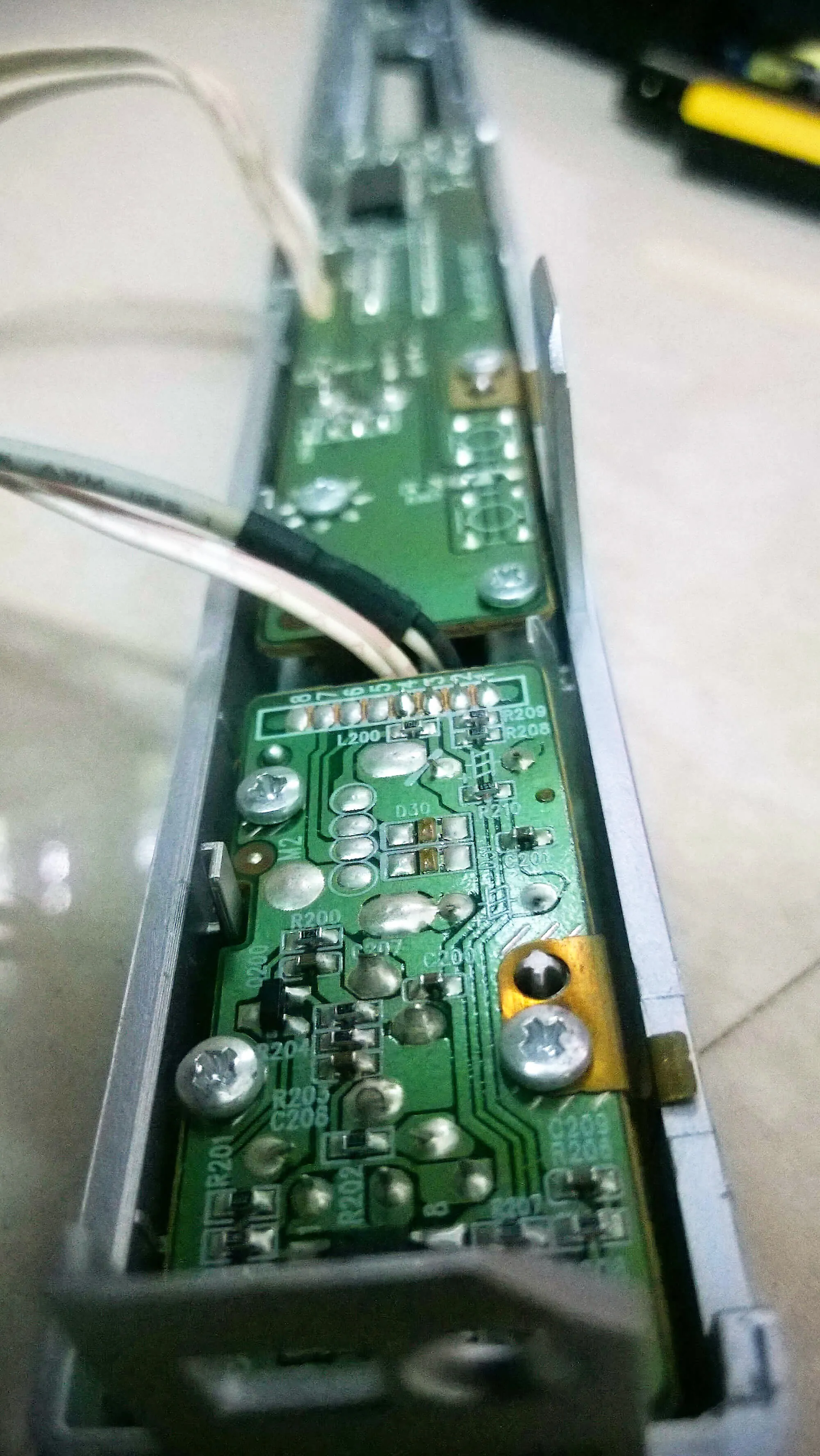
1. The power supply
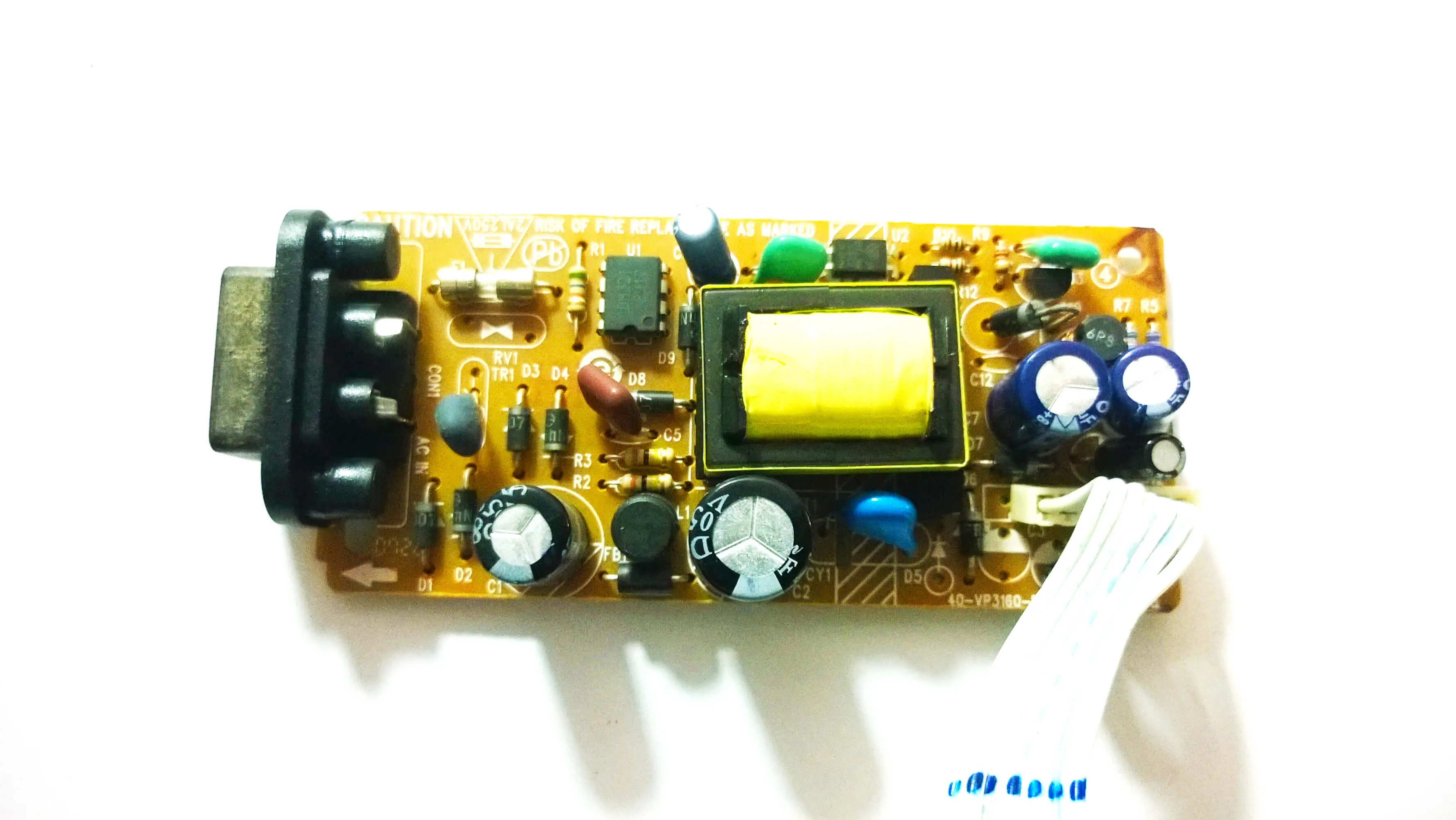
The power supply is perhaps the best thing to salvage from such a device and is totally worth the time.
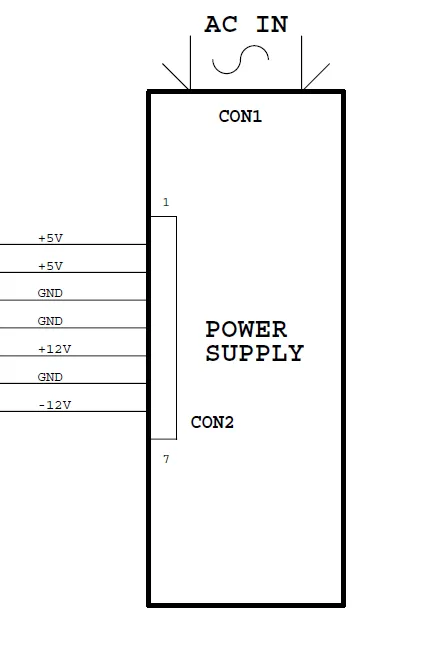
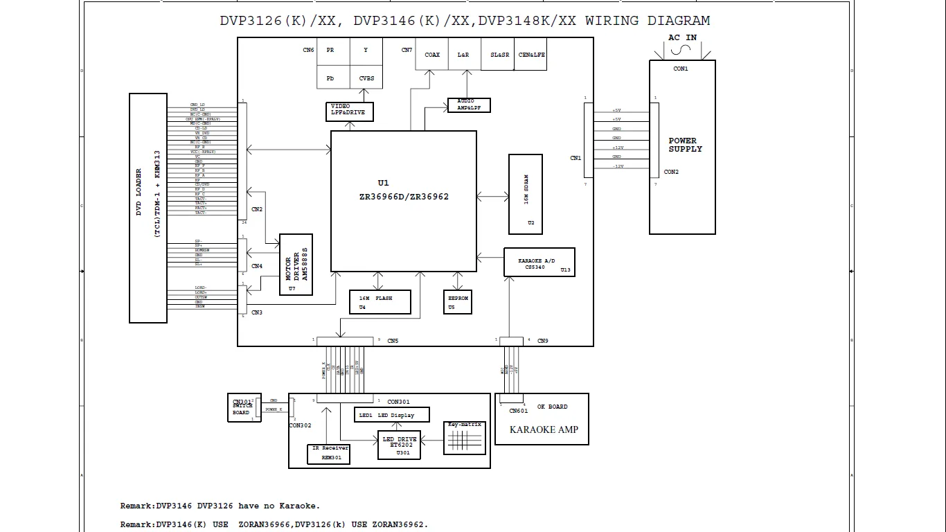
From the service manual I got to know the voltages at the different connector pins. I was pleased to find 5V, 12V and -12V all regulated DC outputs from a single board.
I could use this to run opamps that need voltages at both polarities and well I needn’t explain the potential use of a 5V supply :P
And all this was present as a single isolated board.
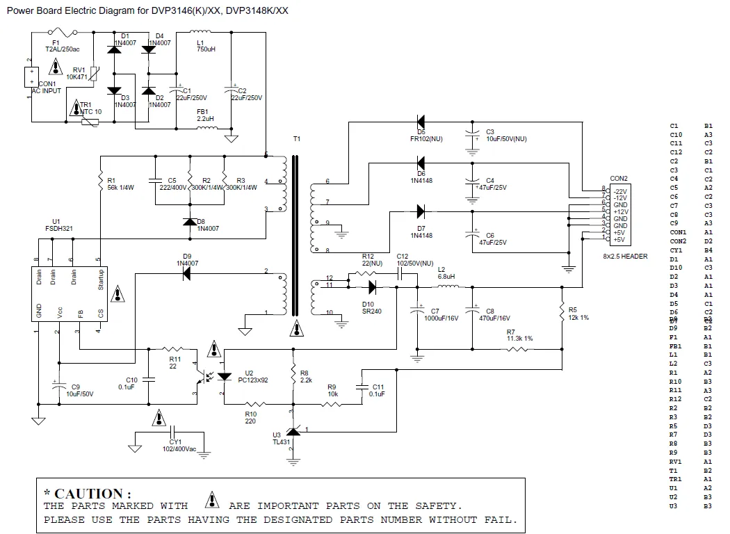
From the diagram below it was quite obvious that this is a well designed and stable supply.
 Update : 20/5/2019 : After lying around for a while, I finally made use of the power supply board to charge lead acid batteries. To bring down the voltage to the required levels I used a regular buck converter module.
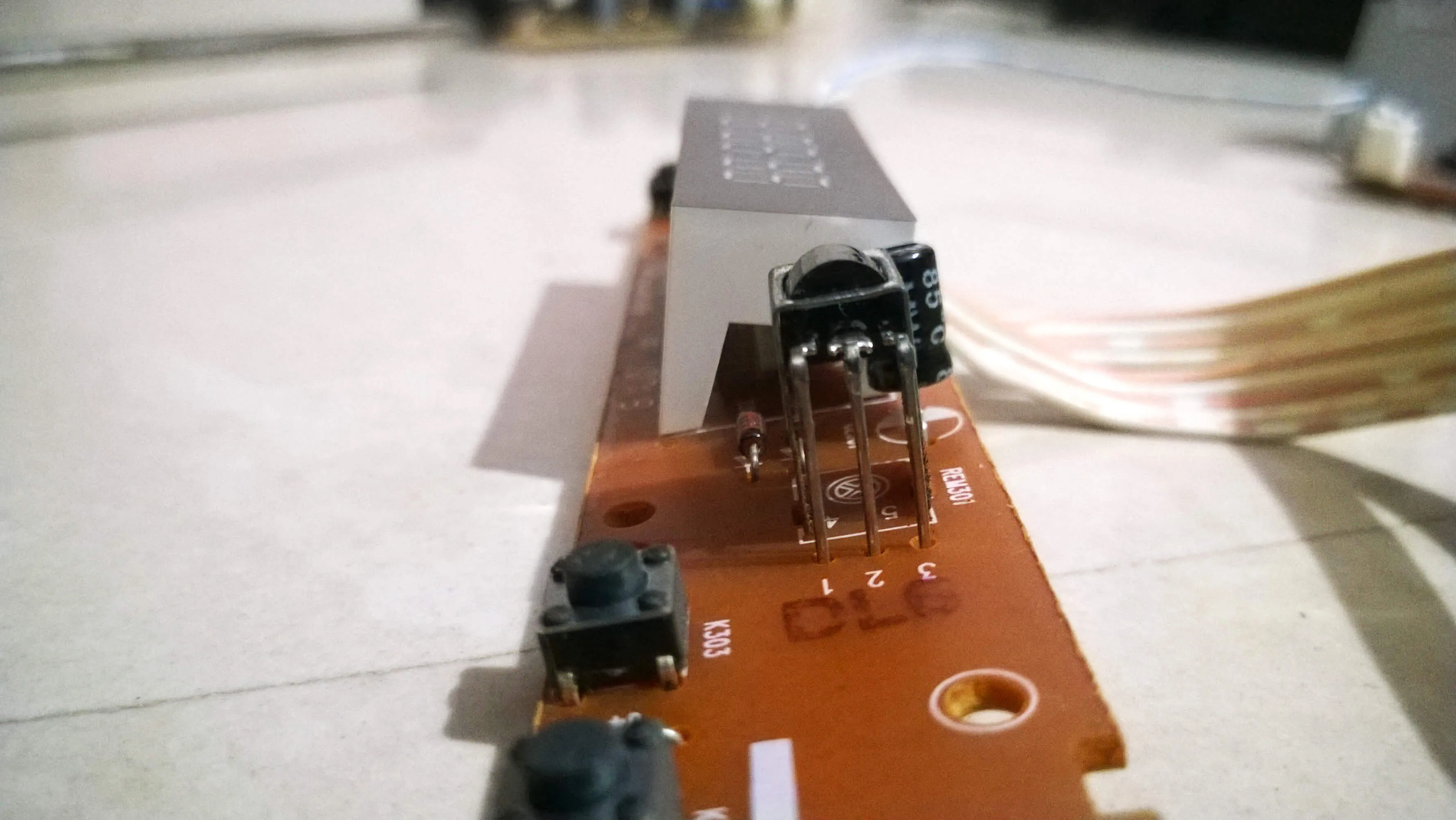
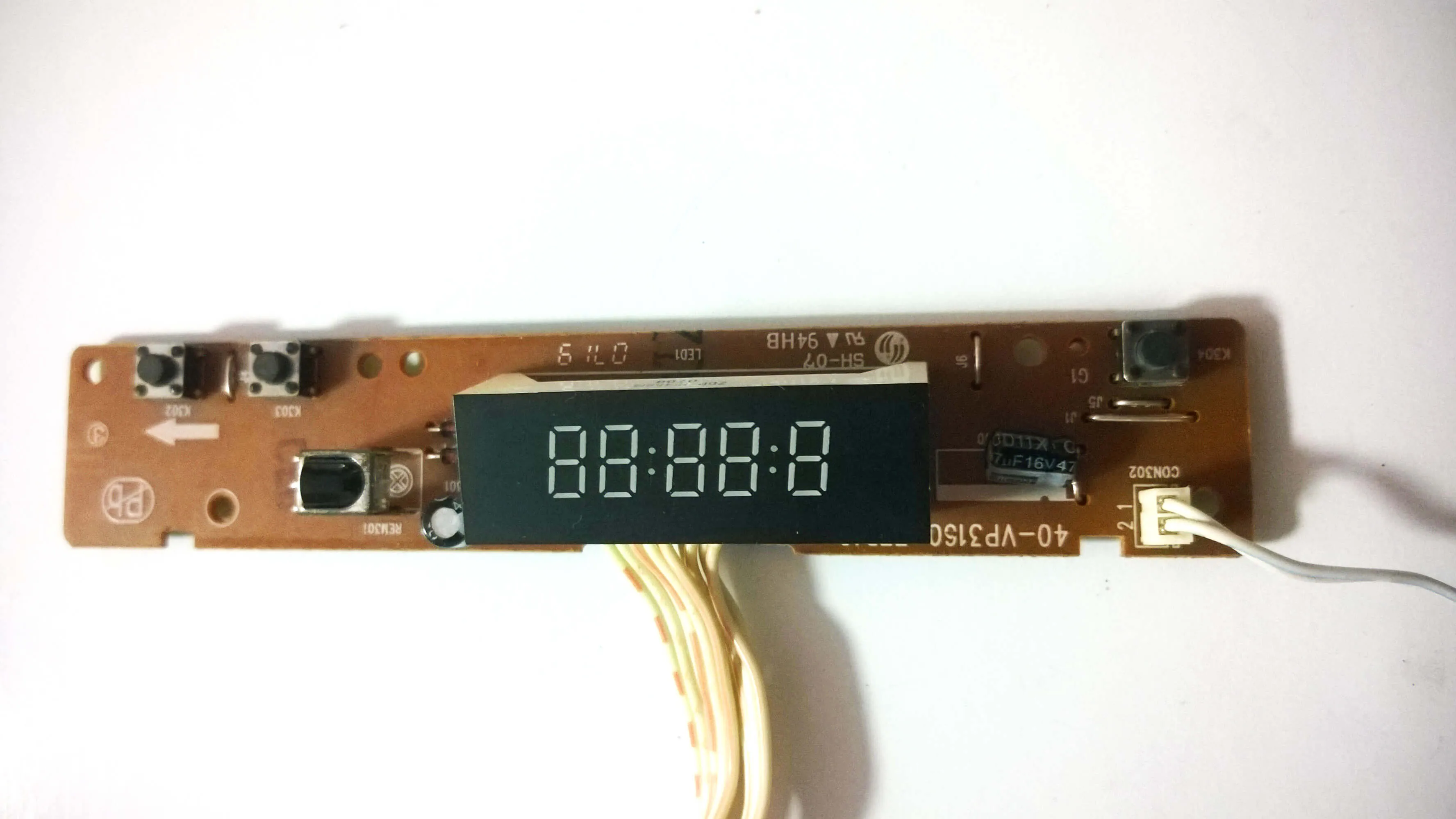
2. The Front Board
The front board consists of the following parts:
- IR module
- switches
- LED display
- Mic with amplifier
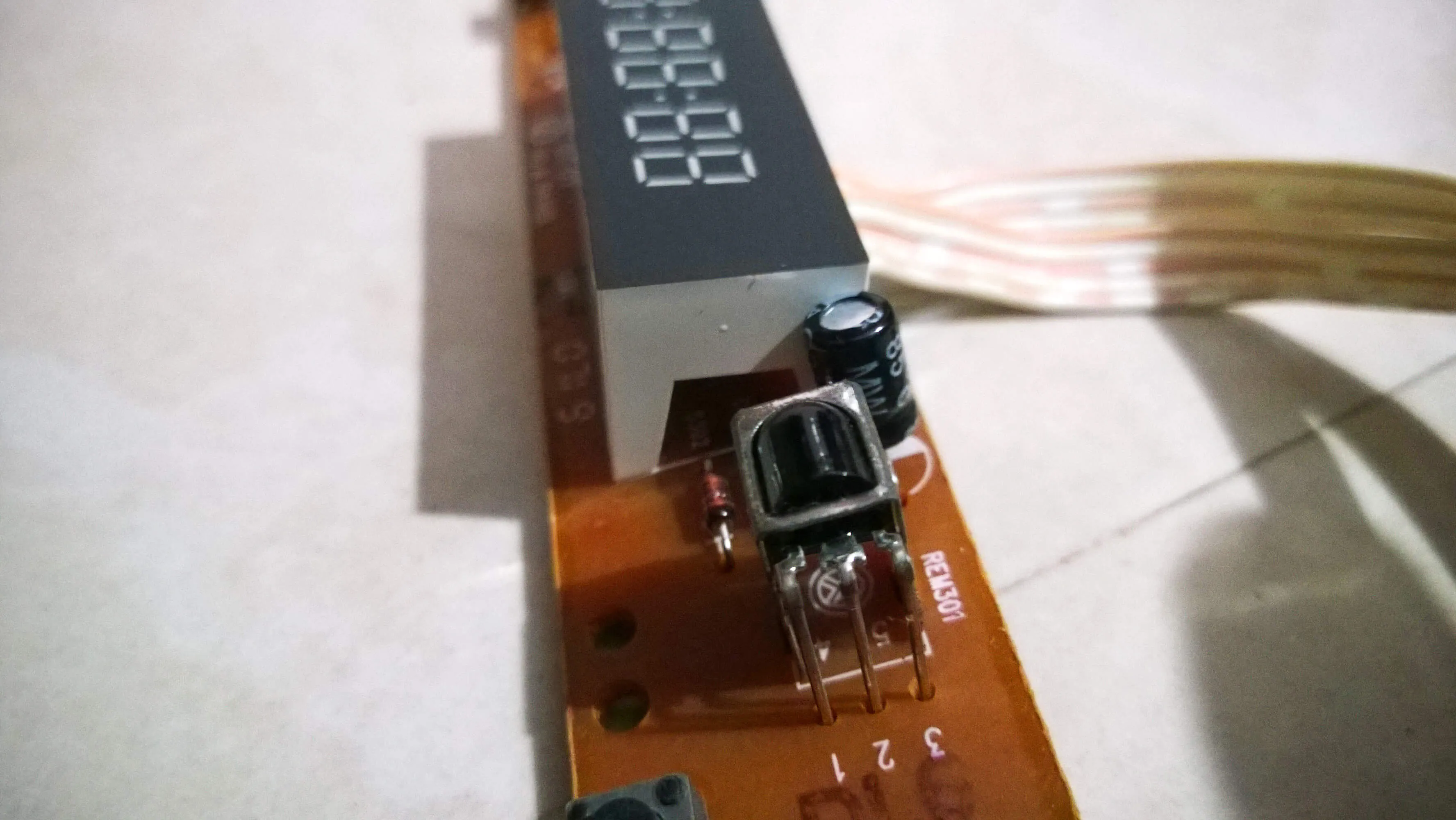
Looks like those standard 3 pin IR LEDs out there.
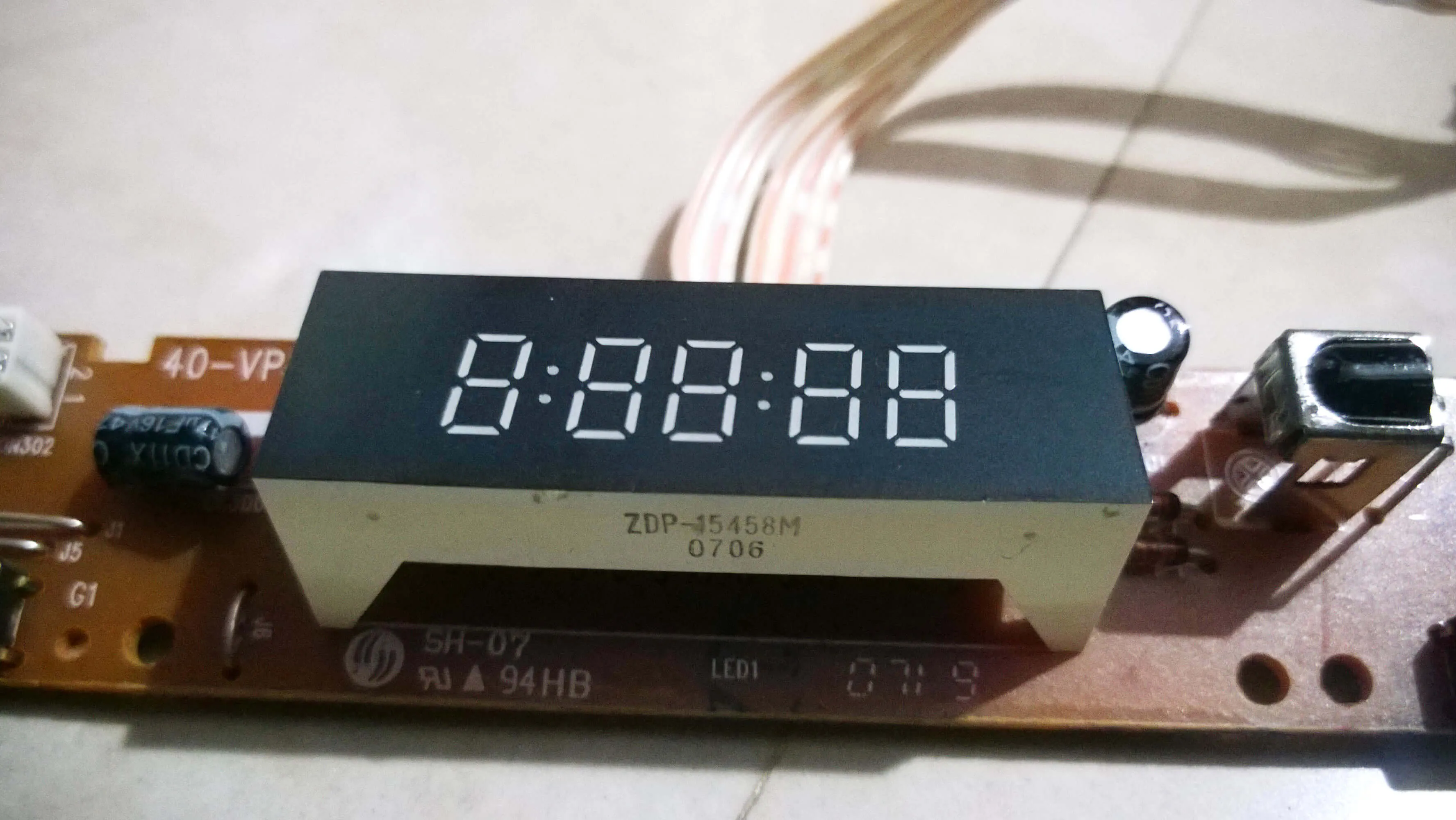
The display uses a ET6202 LED driver which appears to have been used with an arduino too (check this). So this looks like a good catch!
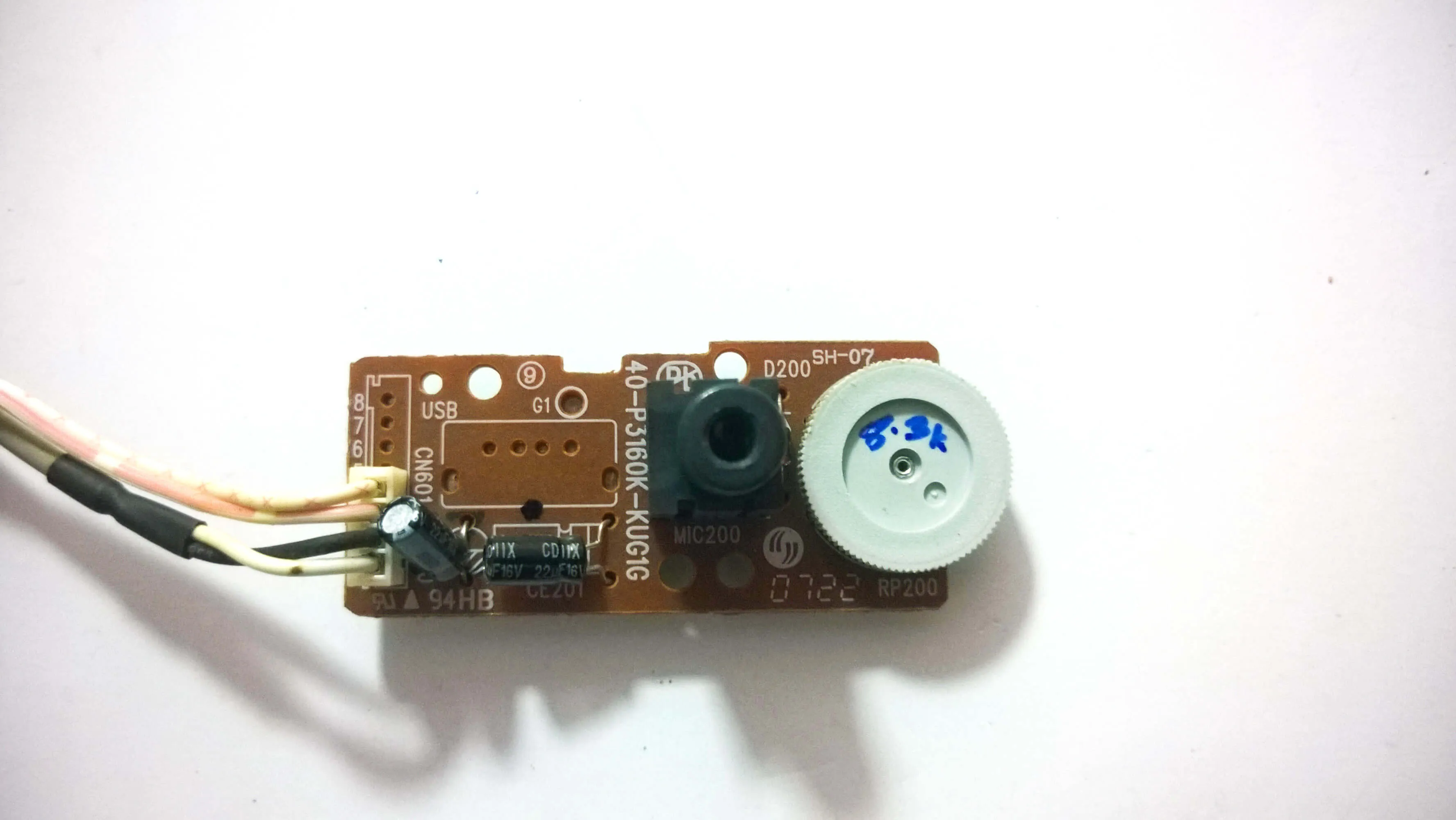
This board had a mic, an 8.3K potentiometer ( measured it using a multimeter), and an amplifer. The pot is used to adjust the gain of the mic.
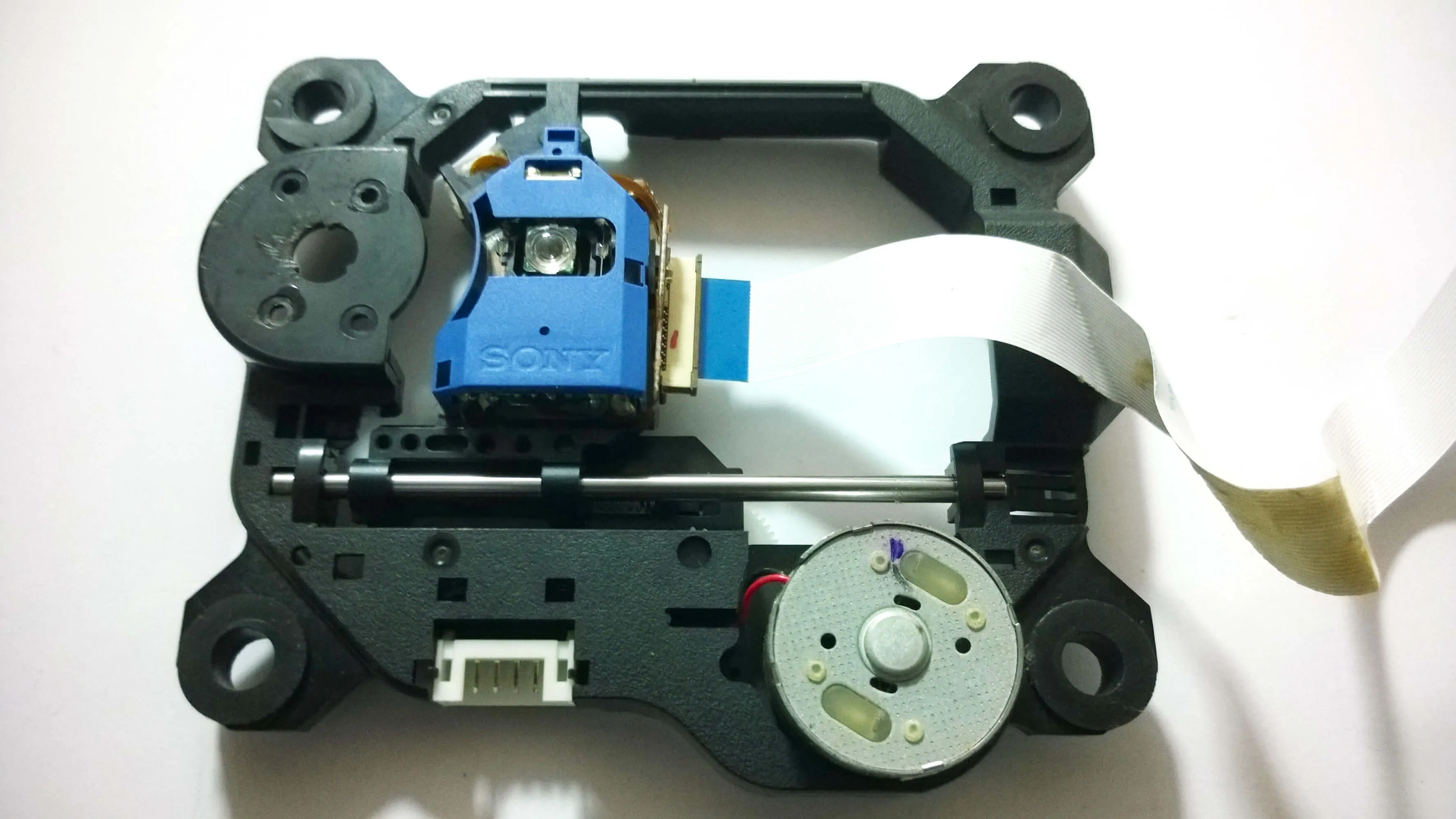
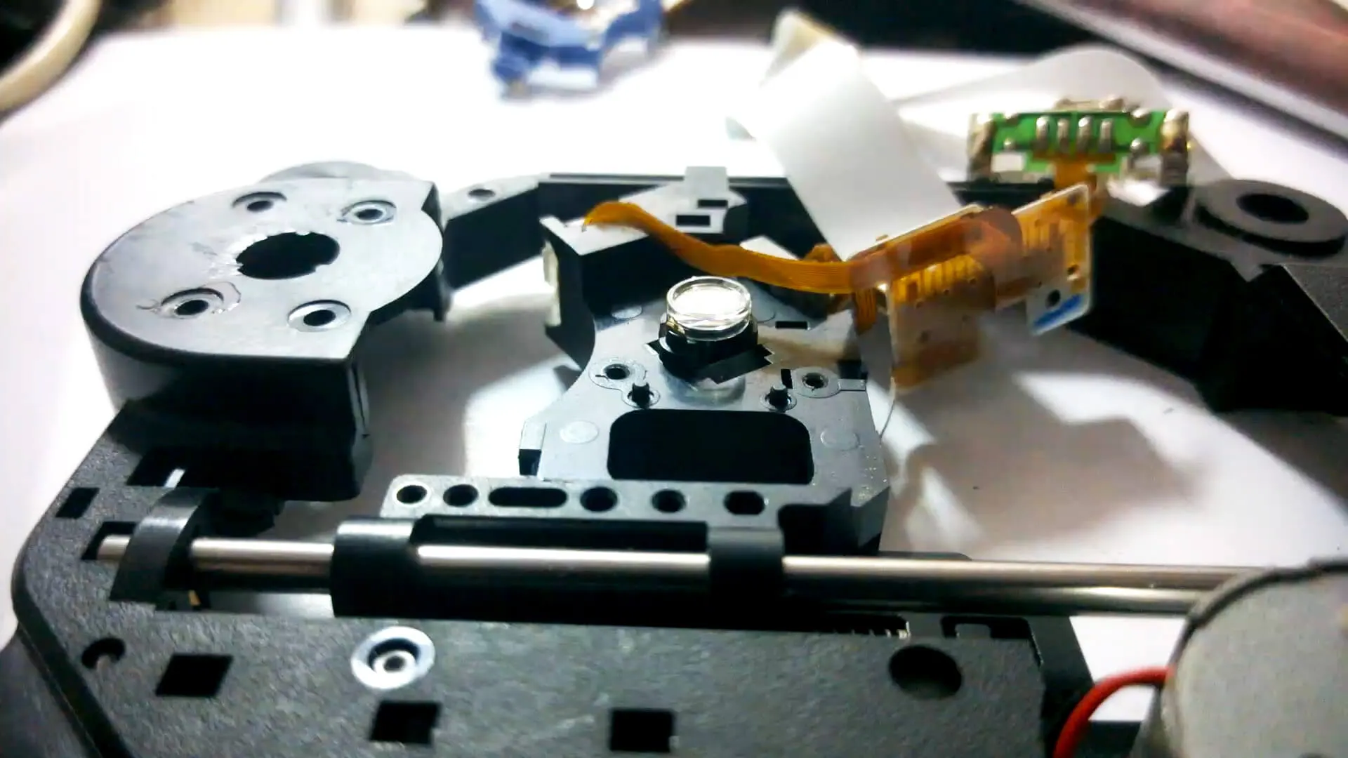
3. The DVD tray
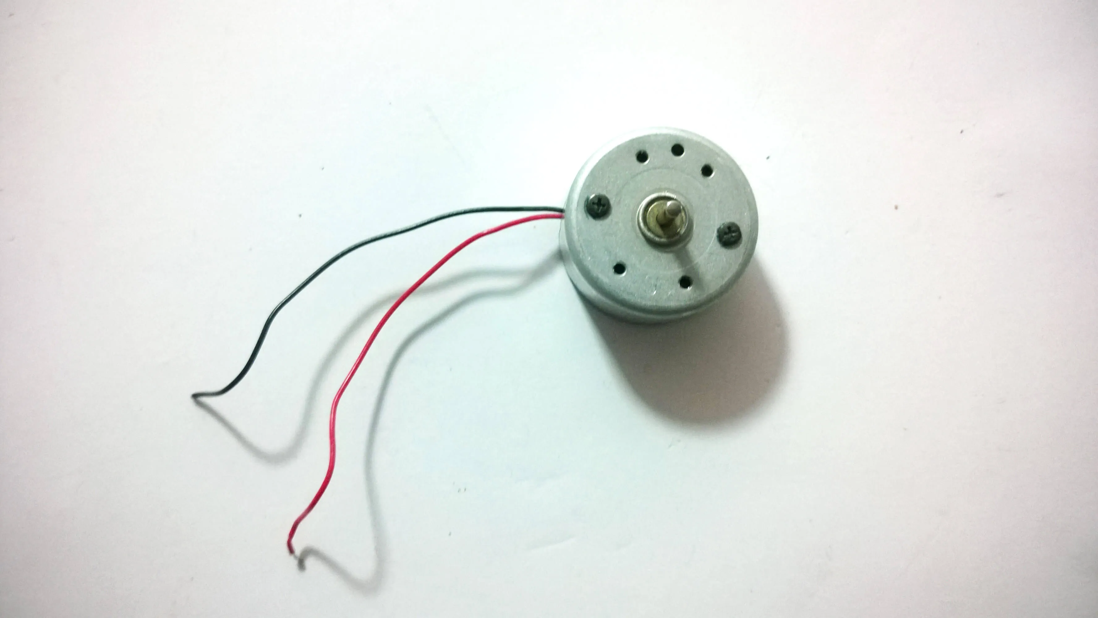
3.1 Motors + a wonderful switch
[enter video here]
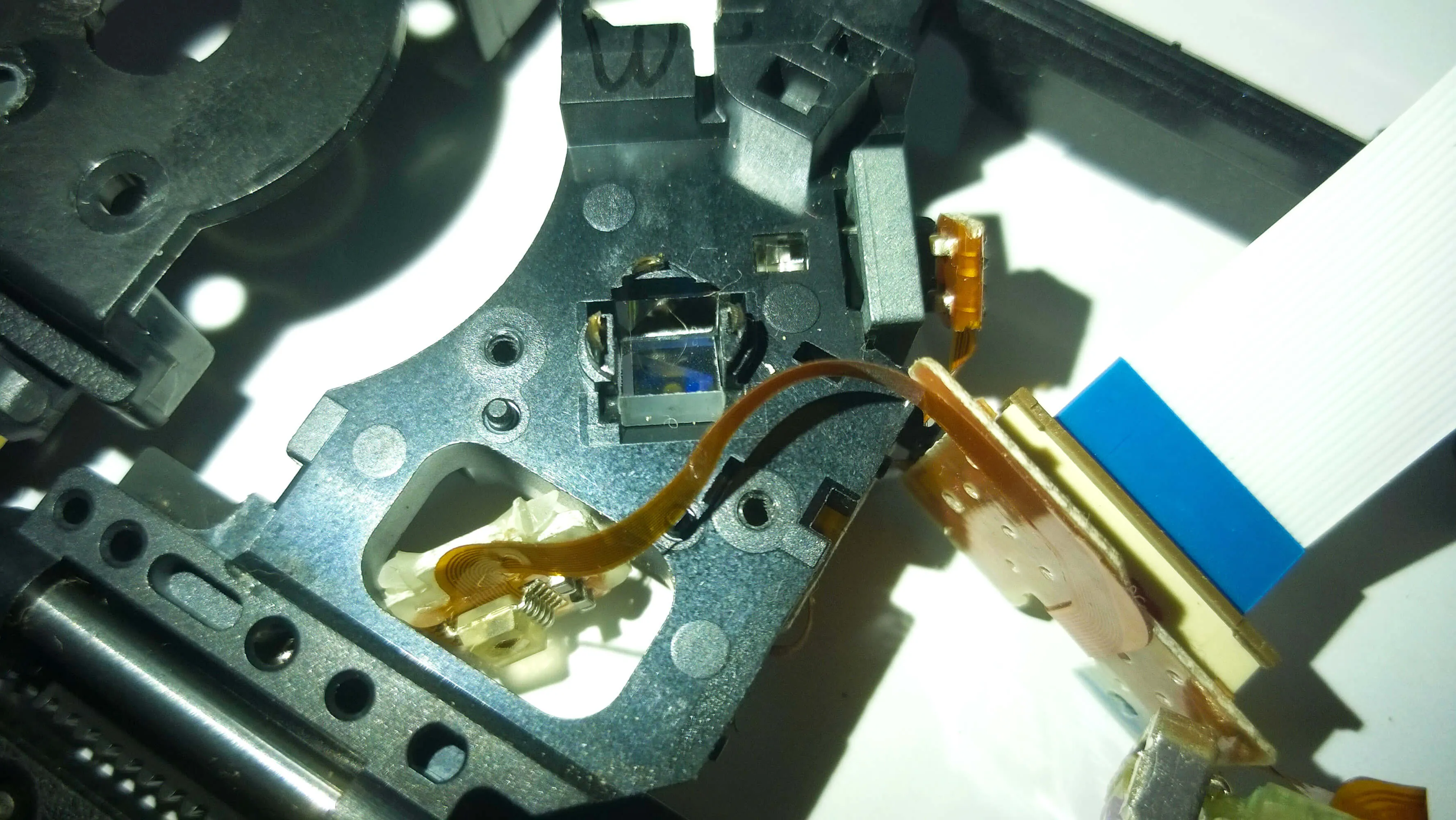
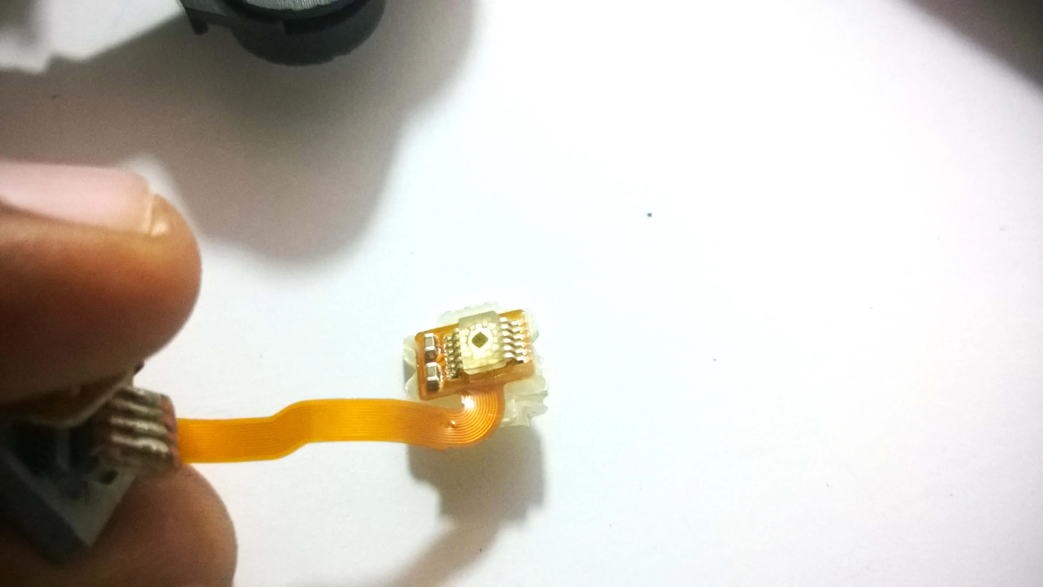
3.2 Lens, Neodymium magnets and more…
Took a closer look and found that the optical reader was from SONY.
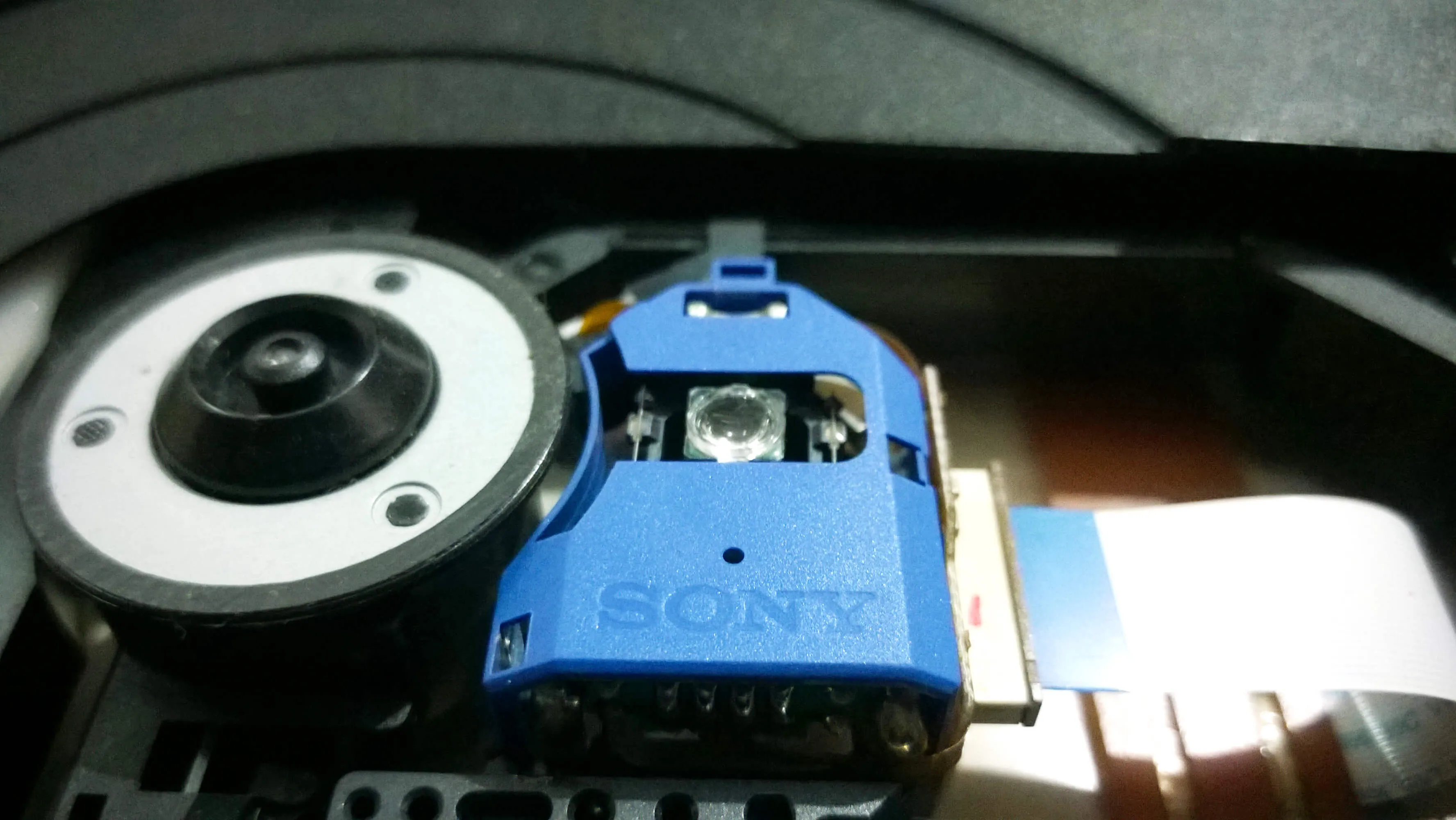
Scraped off the white drop of glue (visible in the above images) and removed the outer cover.
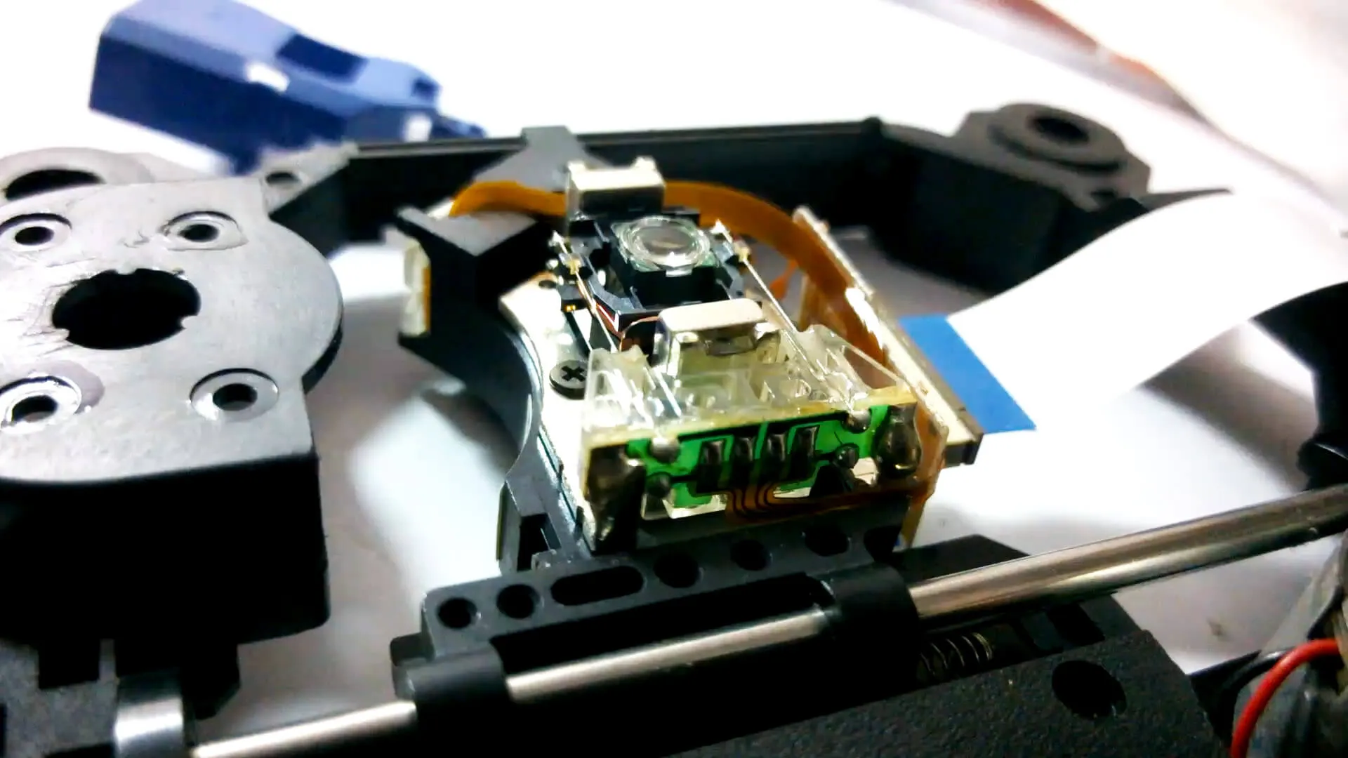
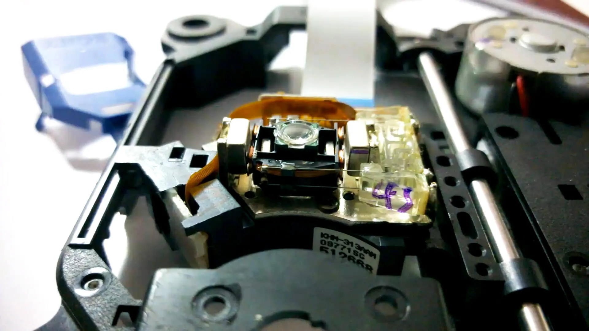
Yoohoo…Time to play around with it…
The above shown are images I took with the lens supplementing my phone camera. The fingerprint ridges look so deep!!
The lens when held above a phone’s screen, the pixels are perfectly visible. The different combination of RGB LEDs that create wonderful images on screen. Beautiful.
3.3 Motors
3.4 Linear Slider
4. What remains:
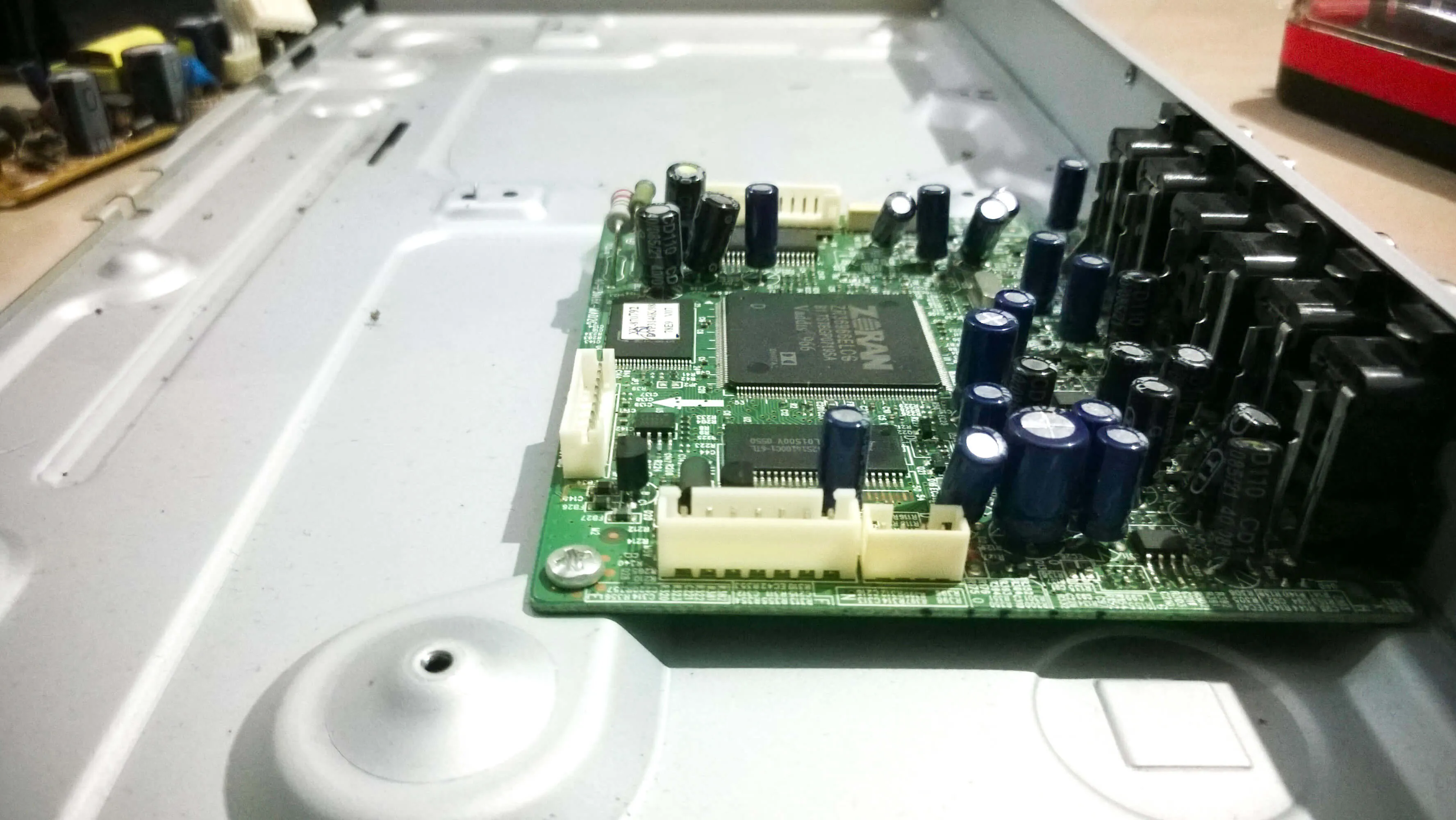
This board is mostly made of SMD components that are not so easy for hobbyists to handle. Though the board has components like
- EEPROM
- SDRAM
- FLASH
- VIDEO DRIVER
- MOTOR DRIVER
the time and money you put into making some use of it will far cross the actual value of the component. Hence I usually discard them.
Comments