Making an ISP programmer for the ATTINY85
![]()
Setting up a circuit every time you need to burn something into the Attiny85 is so cumbersome. So I decided to make a shield to get the job done easily. I sought help from a lot of online references to go about making this shield.Here the full instructions:
1. The Components
- Arduino Uno (or their other boards with an ATMEGA328 )
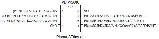
- ATtiny85
- 10uF capacitor
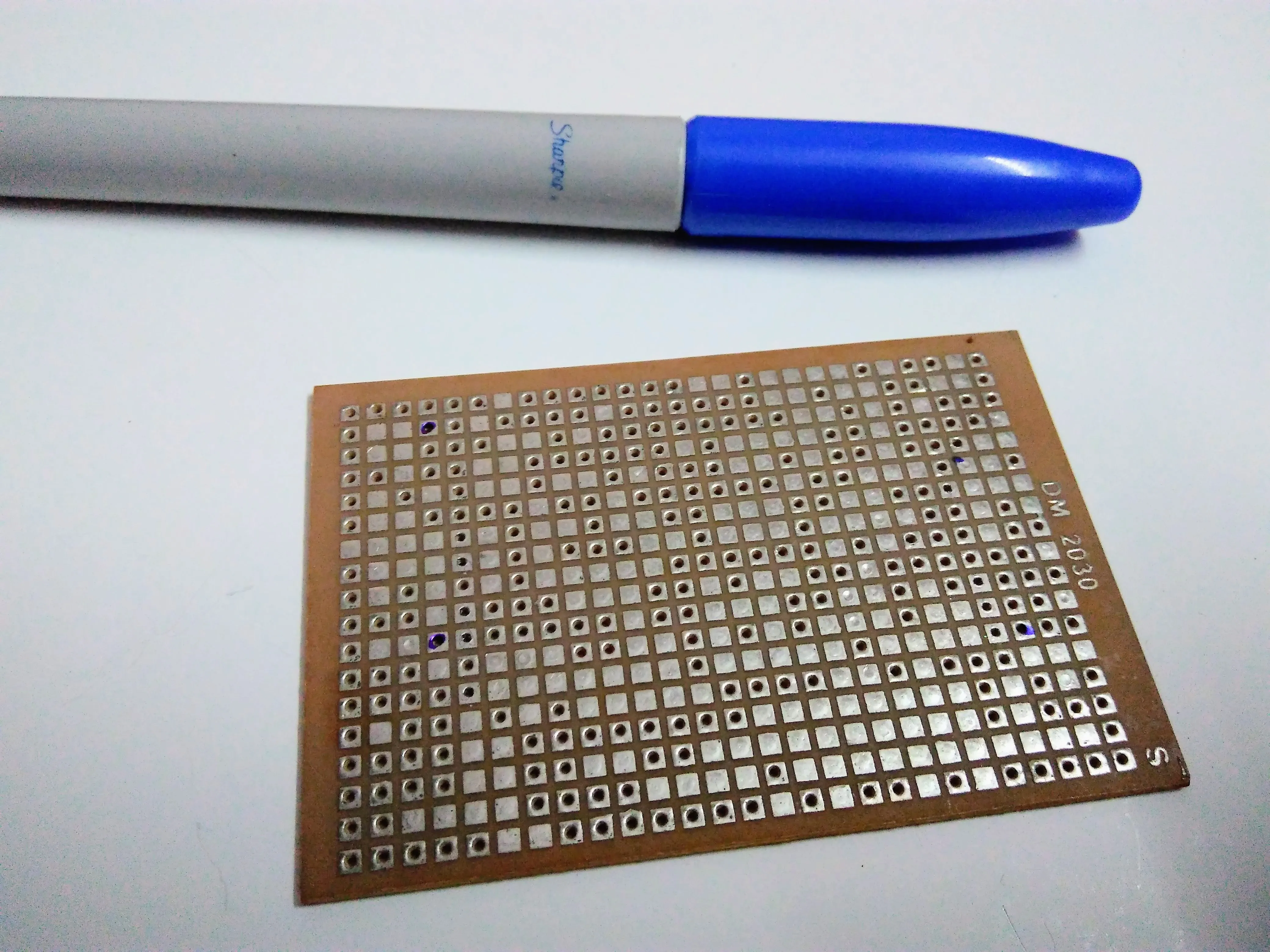
- Perforated board
- Jumpers
- Male header pins
- Female header pins
- IC holder (8 pin)
- LED (to test)
- 330 ohm resistor (to test)
2. Prerequisites
- Install the latest Arduino IDE from arduino.cc
- Open the IDE and go to Preferences which can be found in the File Menu.
- Then in the Additional Boards Manager URLs field add the following URL: https://raw.githubusercontent.com/damellis/attiny/ide-1.6.x-boards-manager/package\_damellis\_attiny\_index.json
- Click OK
- Then open the Boards Manager from the Tools -> Boards
- Wait for the database to update itself
- Search for ATtiny85 and install the board
- Then open the Examples in the File Menu and select the Arduino ISP example program
- Then upload this to your Arduino Uno
- Now you’re all set to program the ATtiny85 with your Arduino.
3. The Circuit
Before directly soldering stuff, it’s highly recommended to try everything out the conventional way on a breadboard and see if everything works well.
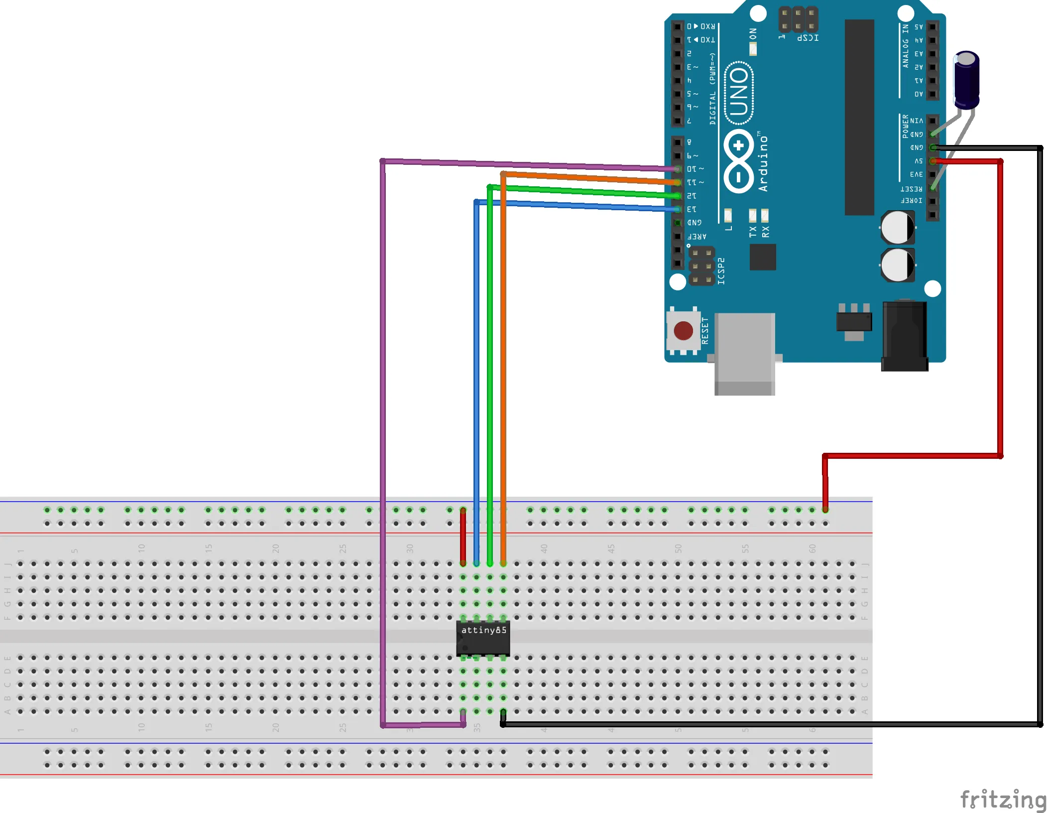
After making the connections, in the IDE do the following:
- Go to tools and change the board selection to ATtiny25/45/85
- Select the processor as ATtiny85
- Clock as ‘1Mhz’
- Select the COM port to which your Arduino is connected
- Select programmer as ‘Arduino as ISP’
- Then open an example blink code and make the output pin as Pin 3
- Then click on upload and the code gets burned onto the ATtiny85.
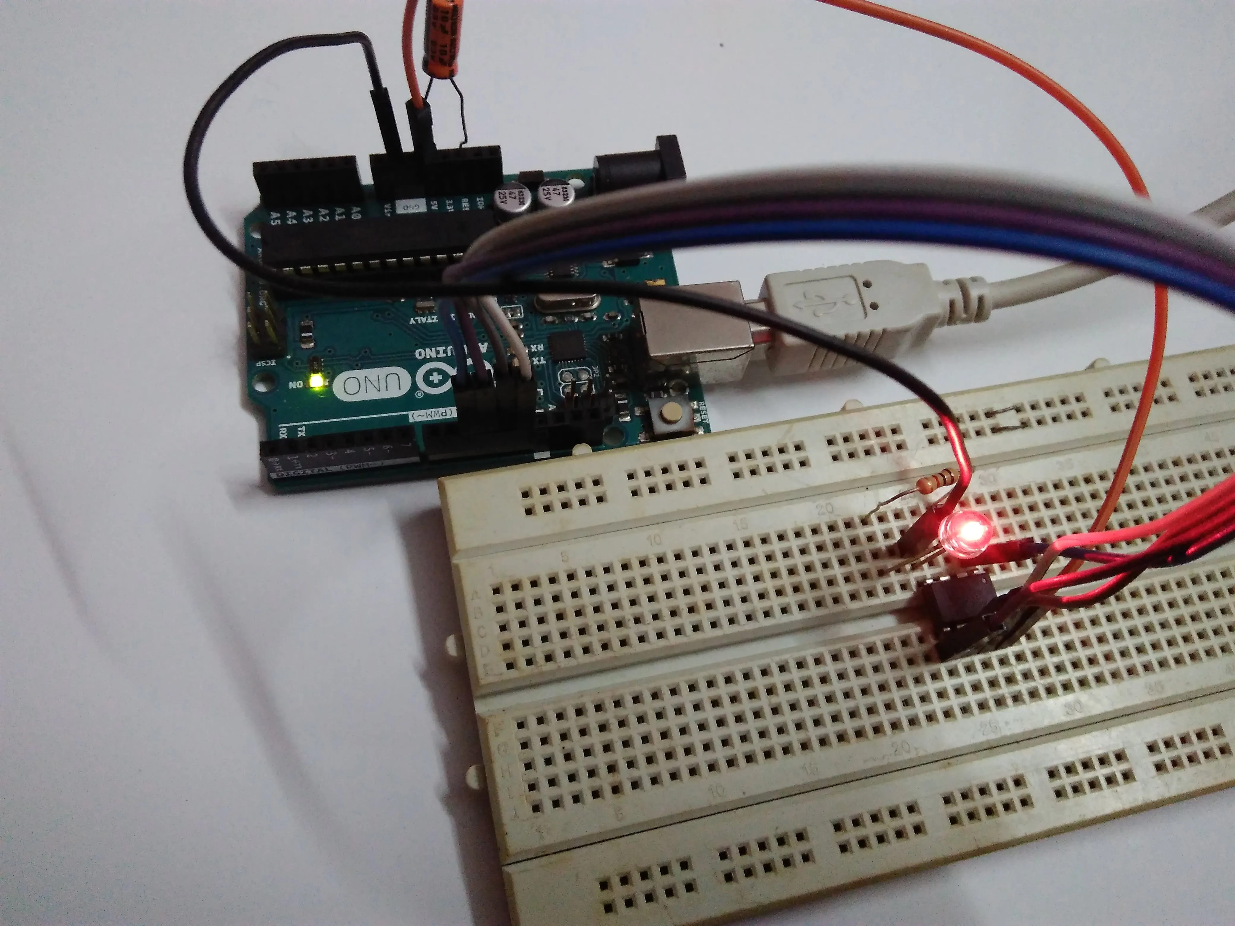
- To test just connect an LED to pin3 and see if it’s working.
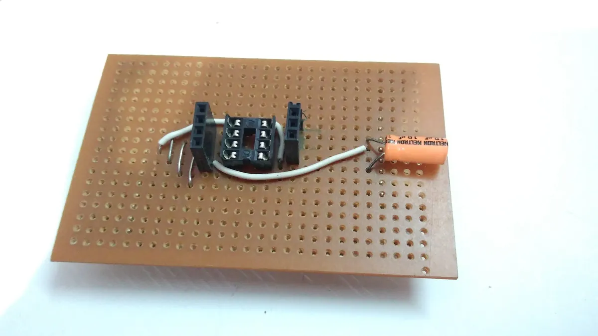
4. Making the shield
I made the shield in the following order. Feel free to do it the way you like it.
- Cut the perforated board in the required dimension
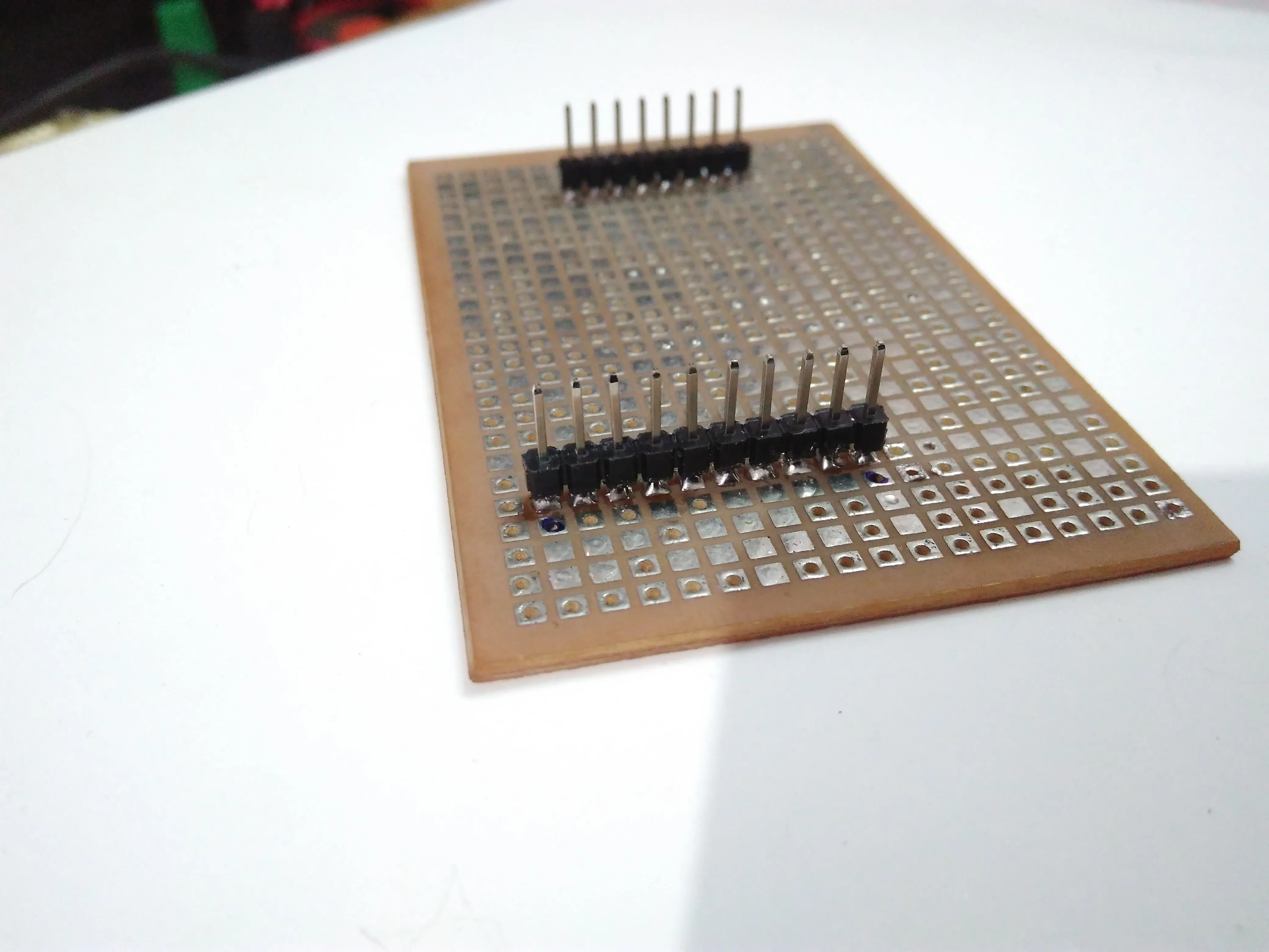
- Break the male headers to the number required for the shield i.e to fill the 2 required female headers of the Arduino
-
Mark the positions where the male headers need to be soldered.
-
Solder the male headers and check if it properly fits on top of the Arduino
-
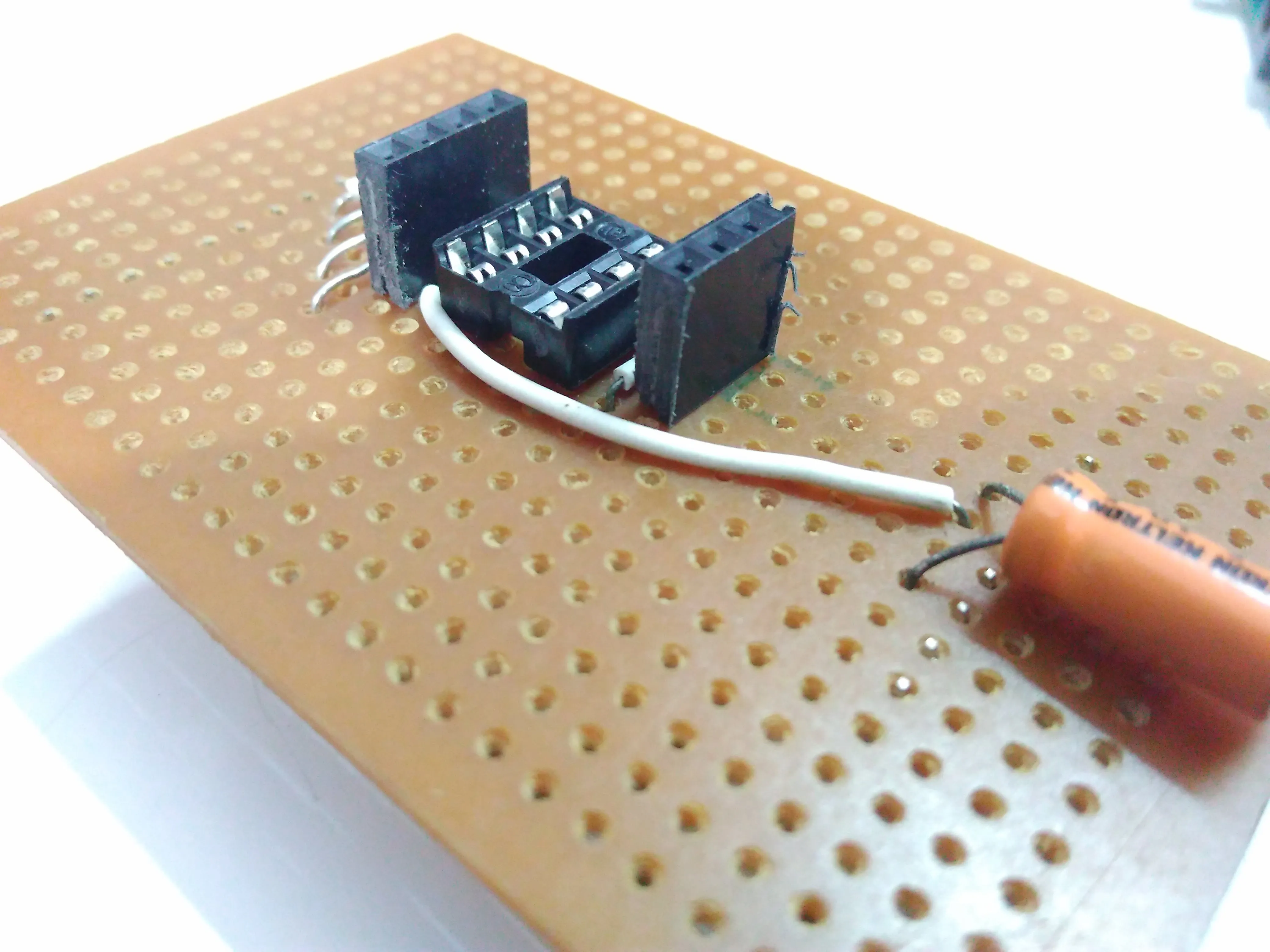
Solder the IC holder onto the perf board in the centre
-
Solder the female headers close to the ATtiny pins (this will help us quickly connect something to test an output directly )
-
Then make the connections using a solder bridge or wire.
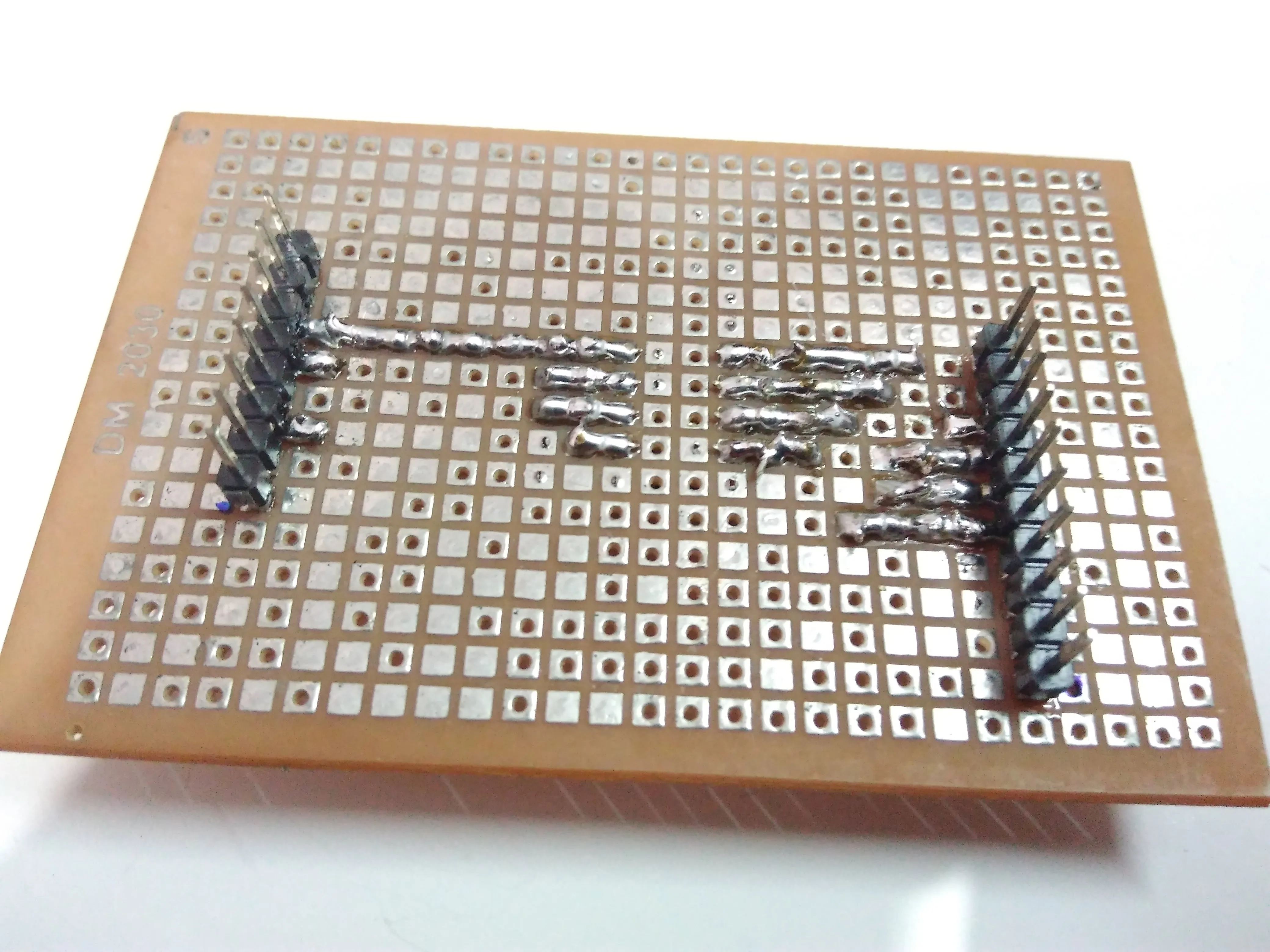
-
Connect the capacitor as mentioned above.
-
Verify all connections and ensure that there is no unwanted solder bridges, using a multimeter set to continuity mode.
-
Plug in your ATtiny85 and you’re ready to go!
-
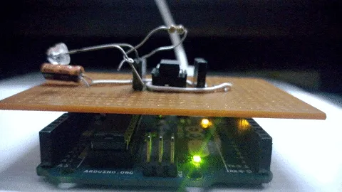
Burn the sample blink code onto the microcontroller as mentioned above.
-
Connect an LED through a resistor(ofc :P) and check if it works. 😁
Comments