1.0 Blink
If you like to start with assembly language programming of the TI-MSP430 check out this awesome tutorial series ( ESE101) on embedded.fm. It took me a whole day to run through all the things in the series. It unfortunately stops at the introduction to programming the device with C. So here’s my attempt to best cover everything that should have come after ESE101.
The Blink example is the ‘Hello World’ of the embedded world. This example just blinks the onboard LED.
Every main.c file that you write must have the msp430.h header. If you are using the Code Composer Studio (CCS) then simply calling msp430.h will do and the compiler automatically pulls up the appropriate header based on your device. In this case it is the msp430f5529.h file.
The MSP430 devices enable the Watchdog Timer by default and if it is not being used we have to turn it off, or you’ll end up resetting your device every now and then. For now this can be ignored and thought as something you need to do in every program that you write.
The WDTCTL = WDTPW | WDTHOLD; does this. More details later.
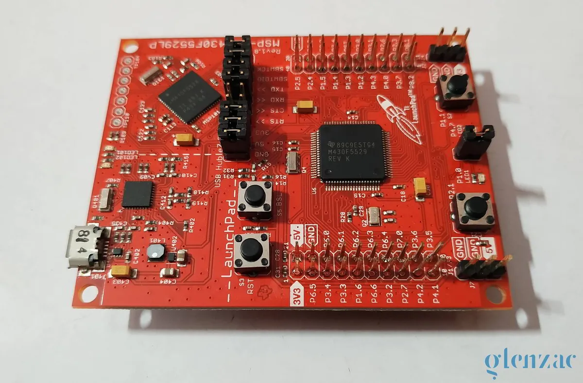
The MSP430F5529 has 63 GPIO pins that are grouped into ports.
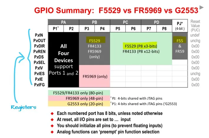
The registers are what we need to understand as of now. The ‘x’ in the register names means they can be replaced with any of the Port numbers like Port 1 ⇒ P1
Here’s the summary of all the registers and their functions:
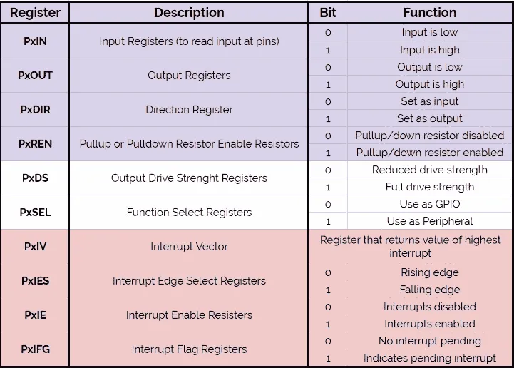
The first four registers (colored in a shade of purple) are what we should focus on now. We need to first set the PxDIR register. Since our LED1 is on P1.0 this means that it corresponds to Port 1. Hence we need to set it as OUTPUT first. We need to set BIT0 of the P1DIR register this can be done using :
P1DIR |= 0x01; another way to do this is : P1DIR |= BIT0;
If you’ve no idea what I’ve just done, just check this guide on bit manipulation.
P1OUT ^= 0x01; This line of code simply toggles the first bit in P1 output register. Thus toggling the state of the LED. Finally, we have a simple for loop to give the required delay. Alternatively, we could use the _delay_cycles() function too. But the point of this whole series is too move away from the easy Arduino style programming practices. (I’m in no way implying that the for loop is any better, in fact it’ still the same, we’ll come across a more power efficient solution in an upcoming example - using timers )
Every program will have a main loop and you want the microcontroller to be running and doing tasks until the supply is cut. Thus you also have a while(1) infinite loop. If you’re coming straight from the Arduino word this can be said to analogous with the void setup() an void loop() that you have there.
/*
 * Created on Sat Jul 11 2020
 *
 * Created by: Glen Zachariah
 * For more: https://glenzac.wordpress.com
 * License: CC0 1.0 Universal
 *
 * For MSP430F5529LP
 * --------Hardware------
---
 * LED1 -> P1.0 (Red)
 * LED2 -> P4.7 (Green)
 * Button S1 -> P2.1
 * Button S2 -> P1.1
 * ----------------------
---
 */

#include <msp430.h>

int main(void)
{
	WDTCTL = WDTPW | WDTHOLD;		// stop watchdog timer
	P1DIR |= 0x01;				// configure P1.0 as output

	volatile unsigned int i;		// volatile to prevent optimization

	while(1)
	{
		P1OUT ^= 0x01;			// toggle P1.0
		for(i=50000; i>0; i--);     // delay
	}
	return 0;
}
Comments