
Emergency Diver Alert System
This is an ultra-big project that I’m working on and is also my final project in uni which means this is a team project as long as uni lasts.
Divers face specific physical and health risks when they go underwater with SCUBA or other dive equipment. About one-third of all diving related fatalities are associated with an acute cardiac event [Source: https://www.diversalertnetwork.org/health/heart/cardiac-health ] and there is no mechanism in place to alert the crew in case of an emergency.
Important Read: http://www.alertdiver.com/matters_of_the_heart
Solution
A small wearable device that continuously monitors the vital signs of the diver and alerts the crew if needed.
Working
The device consists of a microcontroller that continuously acquires the ECG signal from an analog front-end, through the electrodes connected to the diver’s body. The acquired ECG signals are processed to detect various fatal cardiac events. The signals received are also stored in a micro SD card for further use.
If at all any deviation from the normal sinus rhythm is detected, then an alert message is transmitted through one of the on-board serial communication protocols to the diver’s voice communication system which then relays the emergency information to the crew using the existing underwater communications link. This effectively also eliminates the need for a separate communication system. Once the crew is alerted, emergency rescue operations can be immediately initiated.
Underwater effects
Objective
- To develop a comprehensive diver alert system focused on cardiac events of the diver
- To help improve chances of survival post a diving emergency
- To reduce the number of diving-related deaths and make diving a safer underwater activity
List of Hardware
- Microcontroller - Particle Photon
- Instrumentation amplifier - AD620
- Amplifier - AD8031
- MAX1044
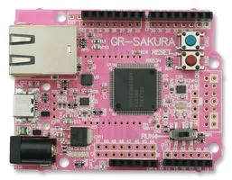
- GR Sakura
- ECG electrodes
Hardware features:
- Instrumentation Amplifier - AD620 **
**- 110dB+ CMRR **
**- Low power - 1.3mA max current
- uV range input offset voltage and drift
- nA range input bias current
High Pass Filter - 2nd order Sallen Key Topology
Low Pass Filter - 3rd order [Buffered RC + Sallen Key]
Block Diagram

Roadblocks
- Once an alert is received how will the crew know where to look for the diver?
Timeline (tentative )
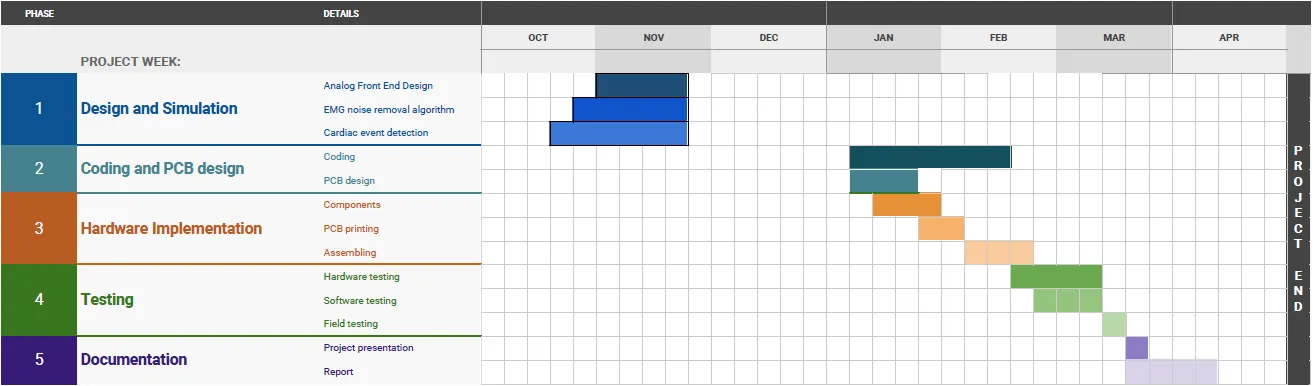
Update: 15/2/18 : Drastic change, I know 😅
Analog front end design
Updates needed in the Multisim circuit :
- Adding the MAX1044 power supply
- Testing with approximate values of resistance
- Adding a level shifting circuit
PCB design
I’d done schematics on Eagle before, but I’d totally no clue of designing PCB’s. The following instructables class helped me get started. https://www.instructables.com/class/Circuit-Board-Design-Class/
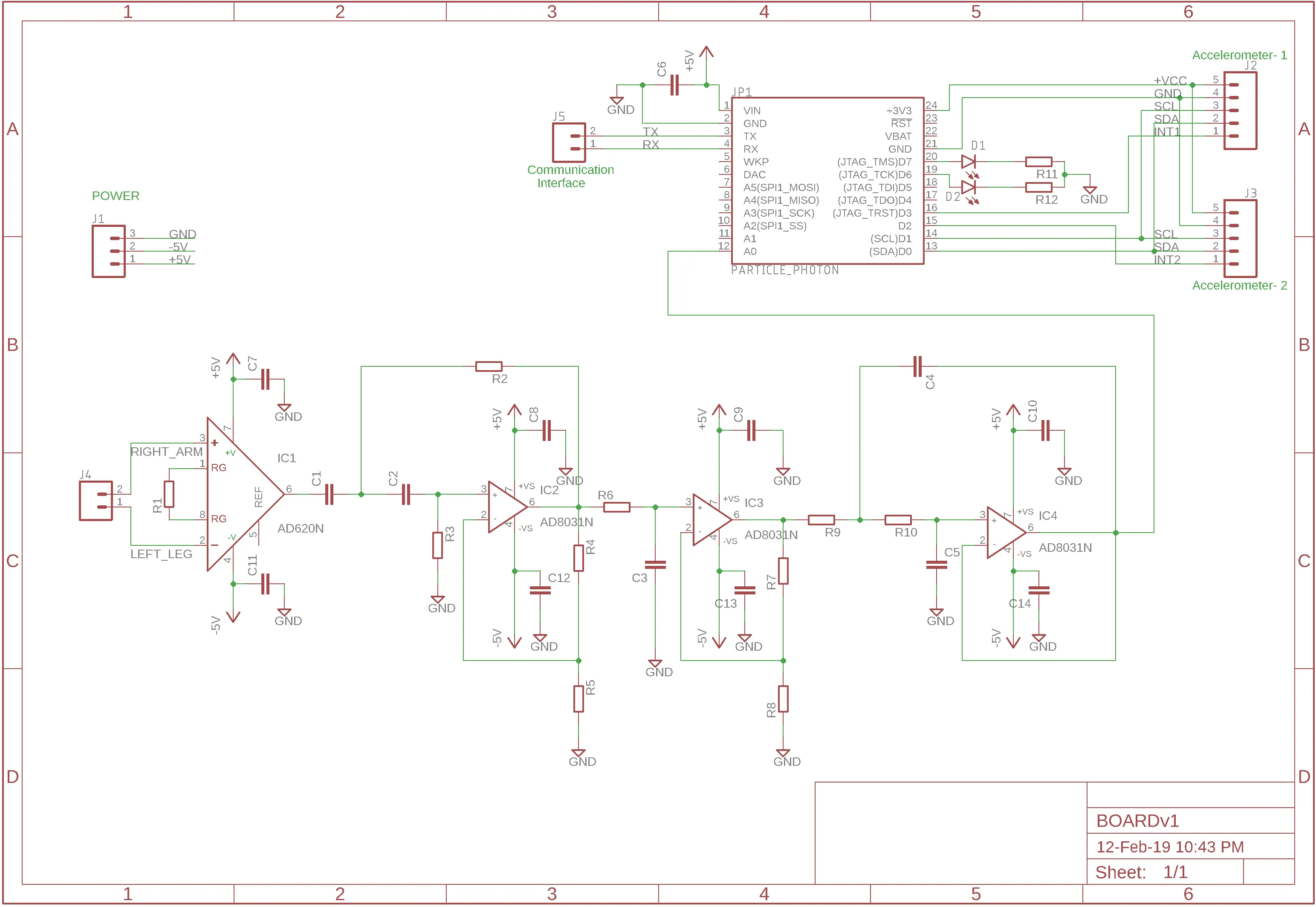
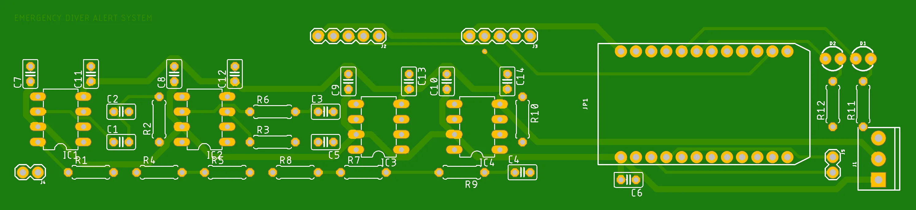
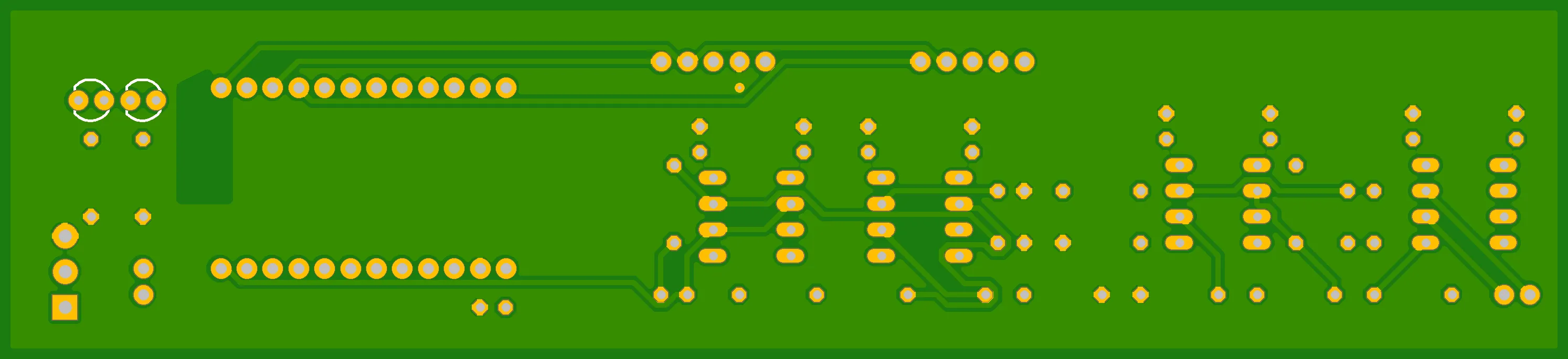
The final schematic looks like this. Decoupling capacitors were added to each IC’s voltage rails. I’ve also added connectors for the proposed accelerometers, power supply and the interface to the voice communication system. Some LED’s too were added to aid in debugging and demonstration.
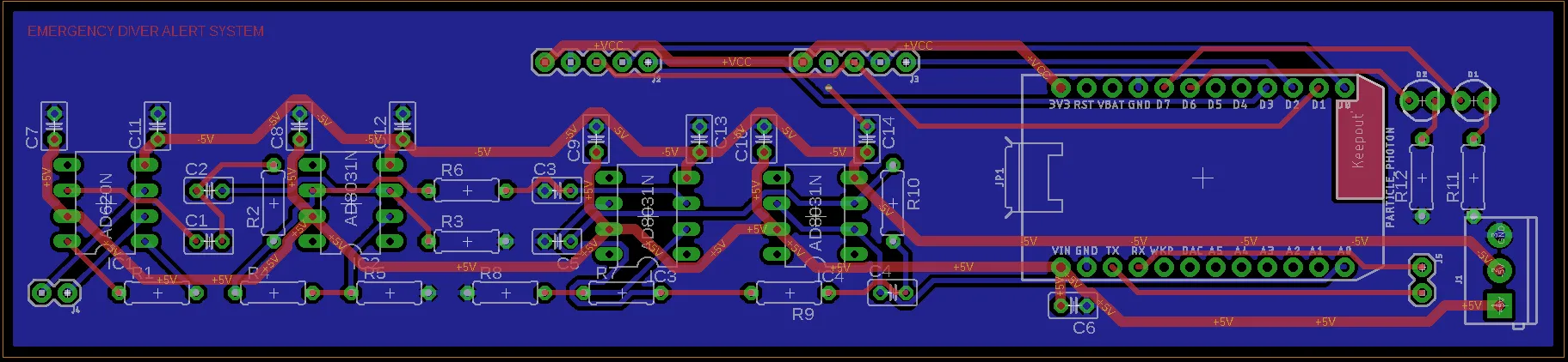
This is the fourth and hopefully the final version of the PCB. I’d to go through a lot of iterations to optimize the design and add connectors at the right places.
Design considerations of the PCB:
- Large square shaped PCB’s are not suitable for use underwater because of the larger surface area. Instead PCB’s are designed to be elongated and which can be inserted into a small cylinder that is attached to the diver’s body. It is here that the area comes into play. Even though spheres have the least surface area for a given volume, it’s often impractical to carry spheres along. Cylinders come next.
One interesting visualisation : http://demonstrations.wolfram.com/RatioOfTheSurfaceAreaOfASphereToACylinder/
Pipes are cylinders and these PCB’s could easily fit into those pipes. - Electrolytic capacitors could pop underwater due to the pressure. Hence the design should rely only on ceramic capacitors. Using ceramic capacitors also had an added advantage of reduced ESR values.
The power rails are the thicker traces in the PCB. The blue background is the ground plane on the bottom layer. I tried to minimize the vias and there’s only one on the board.
Creating test cases for validating the code
It’s hard to come-by a patient with a failing heart to do our tests on 😝. So I needed something to prove that the system would actually work. Got the suggestion to use a DAC to generate the required signals from an expert at college who works on underwater projects. So I got the required ECG signals from the Physionet ATM - signals of 10sec duration and the obtained data had positive and negative values, so were mapped to the DAC’s range of 0-1023. I used the following resource : https://rosettacode.org/wiki/Map_range
The values were a list or in the form of a large column of 600 numbers. The code obviously requires comma separated values. Saving the excel sheet as a .csv didn’t help so I put the column of data from A1-A601 then used a formula in the following column to get the required values.
- Four Test cases:
- normal-sinus-rhythm
- fibrillation
- supraventricular-arrhythmia
- sudden-cardiac-death Even though the particle photon has a DAC, making it simultaneously do all the processing and sampling is going to make it quite slow. Hence I decided to go with an old microcontroller that I had lying around - The Gadget Renesas Sakura board.
Rounding off resistors to their nearest values
2. Moving from 2 supply to single supply
The power source for this device will be 2 lithium-ion batteries in series. (Checkout the Lithium-ion battery charger that I built ). This will give about 7.4V. This voltage is brought down to 5V using a buck converter module based on the LM2596.
#add image here
The DC output was fixed at 5.50V so as to account for the drop across the MAX1044 bringing down the negative voltage rail to -5.0V.
#add image here
4. Contact PCB manufacturer for dimensions and then place mounting holes and spacing
Wrote the fundamentals sections of the code:
1. Reading the ADC and adding values to an array
2. Set up a Software Timer for collecting the time of sampling (is this really necessary? - Needs to be probed since I guess knowing the sampling interval is enough)
3. Smoothing the values and finding max and min. values
3. Implement a cardiac detection algorithm : Going through the list of QRS detection algorithms
2. Implement filters
Demo
To demonstrate the 50% of the project we can’t just show the code. We need to show that the algorithm or the code works. For that, we need to test the code against a test signal. So we need to make a DAC generate the required cardiac fatality signals and give it as input to the microcontroller and see if it detects the event.
PCB add LEDs + motion sensor
Coding :
Filter design tool:
http://www-users.cs.york.ac.uk/~fisher/mkfilter/
-
Analog front end design
-
Photon
-
Why photon? -ADC, speed, DSP, storage, WiFi
-
Timeline
-
Research - variations under water, DSP,
-
Roadblocks- testing
-
Exploring waterproofing solutions
Particle Photon
Reasons for choosing Particle photon:
Particle devices need a connection to the particle cloud for most tasks. It’s a hassle to connect to the internet every time you want to flash something. So in hopes of getting a full local experience I downloaded their desktop IDE which turned out to be nothing but a text editor that to relies on the cloud connection to compile.
Looking more into the issue led me to one of their extensions for VScode called the Particle Workbench that lets you compile locally. I followed all the instructions to set it up on my windows machine. All the processes went well but finally when it came to compiling it threw errors. Errors pertaining to the use of cygwin to run commands on Windows.
The particle community too recommended a Linux build environment. So I had to set up a virtual machine running the latest Ubuntu 18.04 and allotted about 4 GB of RAM knowing I’ll be mostly using Linux after this. I followed the same procedure again Linux setup -> install VSCode -> Install Particle workbench extension.
Tried compiling and I was getting “no gcc arm toolchain found ” errors. The extension should have installed the necessary toolchain. Somehow it did not work. Following discussions on the particle forum I downloaded the toolchain (this is apparently the recommended version ) manually and extracted and placed it in the right location following the following official documentation. I also installed the Particle CLI.
This appeared to do the trick. I was able to compile code locally. The only hassle was that I had to constantly cd between /home/glenzac/Documents/device-os and my project directory. One to compile and the other to flash. The problem came to light when I tried building the firmware when I was offline (apparently when I’d tested this I was connected to the internet and the compiler was calling particle cloud functions to compile :( ). When offline it kept giving cloud compile :443 errors
https://docs.particle.io/support/particle-tools-faq/local-build/
Moving to po-util
Works really well
Changed firmware to SEMI_AUTOMATIC MODE
Moving away from po-util ..
using a virtual machine to flash the photon started to be a pain when the external USB devices weren’t gettting detected in Ubuntu VM at times.
So I finally went back and
New roadblock changed resistor values …rounded values…high gain…level shifting issue
ADC sampling photon : setting the sampling speed
Ref: https://community.particle.io/t/spark-analog-sample-rate-solved/7366/5
Key takeaway : The speed of the loop() will be affected by whether the Core is connected to the cloud or not. Typically, with the cloud connected, the background task will require up to 5ms to run, thus slowing down loop() to about 200Hz on average. With the cloud connection disabled, the loop() will run much faster (The OP got about 25 KHz loop rate with WiFi disconnected) primarily being affected by the servicing of WiFi interrupts and such. It is fair to say that loop() timing is variable and not “reliable”.
Thus sampling needs to be done using timer interrupts. I set the photon to run on Manual mode using :
SYSTEM_MODE(MANUAL);Using software timers:
- Pan tompkins
- pantom online resources - Afonso
- link to qrs detection codes online
- implementing RL driver
- series protection resistance
- Mistake of powering from the mains
Featured image by Francisco Jesús Navarro Hernández on Unsplash
Comments